Download this catalog and see all


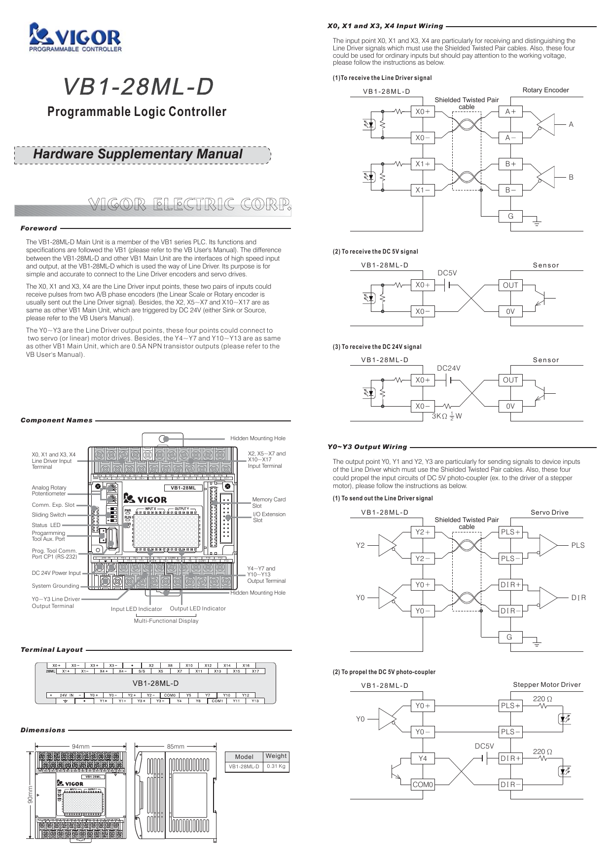
VB1-28ML-D
DC 24V Power input, 4 Line-Driver and 12 DC24V Signal Inputs,
4 Line-Driver and 8 NPN transistor Outputs, the barrier terminal.
Document Information
| Document Title | VB1-28ML-D Specification |
|---|---|
| Document Type | Product Catalog |
| File size | 176.6Kb |
| Product | |
| Category | |
| Company | Vigor Electric Corp., (Documents List) |
Documents related to this company


The content of this catalog(VB1-28ML-D Specification)
Page 1:VIGOR ELECTRIC CORP.ForewordVB1-28ML-D94mm90mm85mmVB1-28ML-D 0.31 KgVB1-28ML24V IN Y0 Y0 Y2 Y2 COM0 Y5 Y7 Y10 Y12Y1 Y1 Y3 Y3 Y4 Y6 COM1 Y11 Y13X0 X2X5X0 X3 X3 X6 X10 X12 X14 X16X1 X1 X4 X4 S/S X7 X11 X13 X15 X1728ML(1)To receive the Line Driver signalX0X1ABX0X1ABGABShielded Twisted PaircableRotary EncoderVB1-28ML-D(2) To receive the DC 5V signal(3) To receive the DC 24V signalX0X0OUTOUTX0X00VSensorSensorVB1-28ML-DVB1-28ML-DDC5VDC24VDC5V3KΩ W12Y0~Y3 Output WiringY2Y0Y0Y4PLSPLSY2Y0Y0COM0GVB1-28ML-DVB1-28ML-DY2Y0Y0PLSPLSD RID RID RID RIPLSD RI220Ω220Ω0VProgrammable Logic ControllerHardware Supplementary ManualThe VB1-28ML-D Main Unit is a member of the VB1 series PLC. Its functions andspecifications are followed the VB1 (please refer to the VB User's Manual). The differencebetween the VB1-28ML-D and other VB1 Main Unit are the interfaces of high speed inputand output, at the VB1-28ML-D which is used the way of Line Driver. Its purpose is forsimple and accurate to connect to the Line Driver encoders and servo drives.The X0, X1 and X3, X4 are the Line Driver input points, these two pairs of inputs couldreceive pulses from two A/B phase encoders (the Linear Scale or Rotary encoder isusually sent out the Line Driver signal). Besides, the X2, X5~X7 and X10~X17 are assame as other VB1 Main Unit, which are triggered by DC 24V (either Sink or Source,please refer to the VB User's Manual).The Y0~Y3 are the Line Driver output points, these four points could connect totwo servo (or linear) motor drives. Besides, the Y4~Y7 and Y10~Y13 are as sameas other VB1 , which are 0.5A NPN transistor outputs (please refer to theVB User's Manual).Main UnitComponent NamesX0, X1 and X3, X4Line Driver InputTerminalAnalog RotaryPotentiometerComm. Exp. SlotSliding SwitchStatus LEDProgarmmingTool Aux. PortProg. Tool Comm.Po t CP1 (RS-232)rDC 24V Power InputSystem GroundingY0~Y3 Line DriverOutput TerminalHidden Mounting HoleHidden Mounting HoleMemory CardSlotX2, X5~X7 andX10~X17Input TerminalI/O ExtensionSlotY4~Y7 andY10~Y13Output TerminalInput LED Indicator Output LED IndicatorMulti-Functional DisplayTerminal LayoutDimensionsModel WeightX0, X1 and X3, X4 Input WiringThe input point X0, X1 and X3, X4 are particularly for receiving and distinguishing theLine Driver signals which must use the Shielded Twisted Pair cables. Also, these fourcould be used for ordinary inputs but should pay attention to the working voltage,please follow the instructions as below.The output point Y0, Y1 and Y2, Y3 are particularly for sending signals to device inputsof the Line Driver which must use the Shielded Twisted Pair cables. Also, these fourcould propel the input circuits of DC 5V photo-coupler (ex. to the driver of a steppermotor), please follow the instructions as below.(1) To send out the Line Driver signal(2) To propel the DC 5V photo-couplerShielded Twisted PaircableServo DriveStepper Motor Driver