Download this catalog and see all


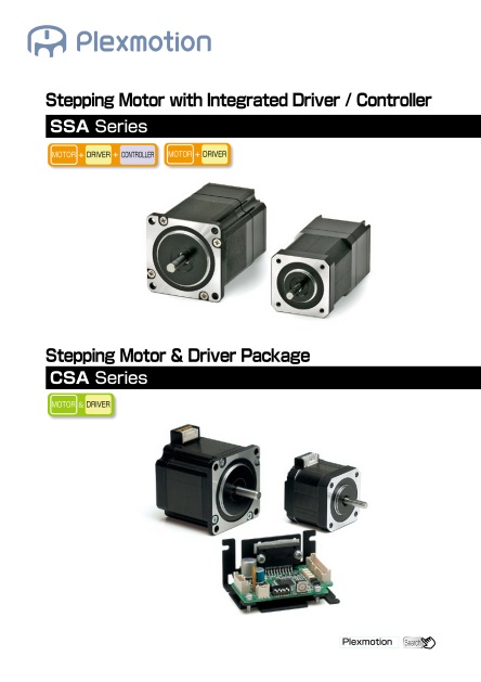
Stepping motor with integrated microstep driver SSA series
Closed-loop Stepping Driver and Stepping Motor Packag Driver & Stepping motor package CSA series
Document Information
| Document Title | SSA series and CSA series |
|---|---|
| Document Type | Product Catalog |
| File size | 10.2Mb |
| Product | |
| Category | |
| Company | Shinano Kenshi Co., Ltd. (Documents List) |
Documents related to this company


The content of this catalog(SSA series and CSA series)
Page 1:SSA SeriesStepping Motor with Integrated Driver / ControllerPlexmotion SearchDRIVERMOTORDRIVERMOTORDRIVERMOTOR CONTROLLER&CSA SeriesStepping Motor & Driver PackageDRIVERMOTORDRIVERMOTORDRIVERMOTOR CONTROLLER&DRIVERMOTORDRIVERMOTORDRIVERMOTOR CONTROLLER&
Page 2:Desired functionDesired deliveryDesired quantity“Plexmotion”®is the authentic standard motor and driver brandpursuing customer usability02
Page 3:SSA SeriesStepping Motor with Integrated Driver / ControllerAppendix / Technical InformationStepping Motor & Driver PackageCSA (Unipolar) SeriesCSA (Bipolar) Series・・・・・・・・・・・▶P.51〜P.22〜P.26〜P.30〜P.38〜P.42〜P.46〜CSA-UA SeriesCSA-BA SeriesCSA-UB SeriesCSA-U ■ Series MotorCSA-BB SeriesCSA-B ■ Series MotorP.04〜P.12〜SSA-TR SeriesSSA-PR/PE Series03
Page 4:POINT1POINT2Simple Setting & Easy OperationSet upText list of each command and settingparameters help instinctive understanding ofeach operation. No programming terminologyand special knowledge are required.ProgrammingProgramstoringMotor installationStarting up“CosmoApp”and making new project file.After clicking“Connect”button, programming session is ready.After installing original software“CosmoApp”and converter driver,simply connect SSA-TR to PC via converter.With pressing“Store in motor”button, programs will be transferred to the motor(Maximum 8 programs).STEP1STEP2STEP3After disconnecting SSA-TR from PC, stored programs areexecutable from external input signals to the motor.① Click command② Set parameter③ Press“Add”buttonRepeat ①∼③ processesfor each command setting④ Press“Execute program”buttonfor program operationInstallingUSB RS-485ConverterPower supply unit1 line program execution or continuousprogram execution is selectable for programconfirmation and revise.FeaturesS SA-T R : St e p ping m o t o r wit h in t eg r a t e d p r og r a m m a ble c o n t r olle r●Integrated controller and driver into motor flange size●Operable in 8 programs with sensors input●Selectable in 4 steps division (Full, Half, 1/4, 1/16)●Input voltage : DC24V●Warning / Error signal output●Optimized design endbell for effective heat dissipation●Easy programming with original application software "CosmoApp"Stepping Motor with Integrated ControllerSSA-TR SeriesUp to1/16microstepping2 phase1.8°/step Controller8ProgramsMotor Driver 04
Page 5:Package Contents1. Controller integrated stepping motor2. Power supply cable (60cm)3. Signal cable(60cm)4. Application soft CD5. Operation manualModel□ Size[mm]Item nameInputvoltage[VDC]Ratedcurrent[A/phase]Holdingtorque[N-m]Motorlength[mm]Motormass[kg]Stepping motorwith integrated controller42.0 SSA-TR-42D4 24 0.8 0.270 84.5 0.4556.4 SSA-TR-56D3 24 2.0 0.880 80.5 0.75Package Model□ Size[mm]Package item nameInputvoltage[VDC]Item namePowersupplyunitUSB 〜RS485converterSSA-TR series& power supply unit42.0 SSA-TR-42D4-PS 24 SSA-TR-42D4◯50W-56.4 SSA-TR-56D3-PS 24 SSA-TR-56D3◯100W-SSA-TR& RS485 converter42.0 SSA-TR-42D4-U4 24 SSA-TR-42D4 - ◯56.4 SSA-TR-56D3-U4 24 SSA-TR-56D3 - ◯SSA-TR series / power supplyunit / RS485 converter42.0 SSA-TR-42D4-PSU4 24 SSA-TR-42D4◯50W◯56.4 SSA-TR-56D3-PSU4 24 SSA-TR-56D3◯100W◯Product LineupTorque Range1.8SSA-TR-42D4SSA-TR-56D384.580.542.056.4Stepangle(°)□ size(mm)Motor length(mm)Model nameModel namePullout torque(N-m)Pullout torque(N-m)0 0.1 0.2 0.4 0.6 0.8 1.0 1.5 2.00 0.1 0.2 0.4 0.6 0.8 1.0 1.5 2.0□ size(mm)Motor length(mm)Stepangle(°)SSASeriesFeaturesSSAPR/PESSATRCSASeriesFeaturesCSA-UA/UBCSA-BA/BBTechnicalInfomation05
Page 6:Stepping Motor with Integrated ControllerDimensions1219・・・120・・・2CN1Pin No.→CN2←Pin No.47.14φ66.674−φ4.547.14□56.4 20±11580.55.81.6φ38.1φ6.35−0−0.013−0−0.03Throughhole20±11584.54.5φ22−0−0.03φ50−0.01324−M3×0.5Depth 4.5min.31□42311219・・・120・・・2CN1Pin No.→CN2←Pin No.※CAD Data (2D & 3D) download pagehttp://www.skcj.co.jp/plexmotion/english/download/Cable Specifications60cm8mm40cm20cm60cm7mmPin number(Cable color)Pin number(Cable color)UL3265 CSA AWM AWG26UL1061 CSA AWM AWG282(BK)1(RD)1357911131517192468101214161820(RD)(YL)(BL)(GR)(BK)(RD)(YL)(BK)(BK)(VT)(BN)(OR)(GN)(VT)(WT)(BN)(OR)(GN)(RD)(BL)CN2 Mating connector : Manufacture : JSTᷨḏḕḓḉḎḇ᷐ᷧᷨᷤᷲ᷒ᷳᷣ᷶᷍᷍ḏḎḔḁḃḔ᷐᷐᷐᷐᷎᷷ᷳᷧᷨᷤ᷒ᷧᷡᷰ᷒᷀᷈ᷡᷧ᷃ᷓ᷍᷍"᷷ᷡᷧ᷃᷒ᷖ᷉CN 1 Mating connector : Manufacture : JSTᷨḏḕḓḉḎḇ᷐᷺ᷥᷲ᷒ᷳᷣ᷶᷍᷍ḏḎḔḁḃḔ᷐᷐᷐᷎᷺᷷ᷳᷥ᷒ᷴᷰᷓ᷀᷈ᷡᷧ᷃᷒ᷘ᷍᷍"᷷ᷡᷧ᷃᷒ᷔ᷉Power Supply Cable Signal CableSSA-TR-42D4SSA-TR-56D306
Page 7:Common SpecificationsInput voltage DC24V±10%Driving method 2 phase bipolar chopper drivingStep division 1 (1.8Deg. / step), 2 (0.9Deg./step), 4 (0.45Deg./step) and 16 (0.1125Deg./step).Signal input 1) Program selection : 3 bit2) Limit sensor 1&2 input3) Origin sensor input4) Seek mechanical home position5) Enable : Motor currentSignal output 1) Ready/Busy : Exciting program signal / No exciting program signal2) Heat warning signal (Over 70Deg. C at case inside)3) Error signalCommunication RS485 InterfaceController Controller type Stored program controllerProgramming Through original software "CosmoApp"Program lines 100 lines for each programNumber of programs 8 programsStart velocity 10[pps] to 10000[pps]Target velocity 10[pps] to 50000[pps]Acceleration/Deceleration time10 to 10000[ms]Acceleration/Deceleration patternLinearOperation 1) Incremental positioning : 0 to 16,777,215 pulses2) Absolute positioning : -8,388,608 to 8,388,607 pulses3) Continuous drive4) Multi velocity5) Mechanical home seek6) Electrical home return7) Jog : through "CosmoApp"Indicator LED : Light on (Power on) / Blinking (Error)Protective function 1) Current fuse : Resettable fuse2) Excessive heat protection : Over 90 Deg. C at driver caseOthers RoHS compliantLocking connectorAmbient temperature 0 to 40 Deg. C. No freezingAmbient humidity 85% or less. No condensingStorage temperature -20 to + 60 Deg. C. No freezingStorage humidity 85% or less. No condensingAtmosphere No corrosive gas, no dust surroundings. No water and oil splash.Motor Specifications* Keep the load within permissible load value. Otherwise, it may cause the shaft to bend or break.Radial load value is measured at the top of the output shaft.Item nameRatedcurrent[A/phase]Holdingtorque[N-m]Maximumstartingfrequency[pps]Rotorinertia[g-cm2]Permissible load *Dimensions(WxHxD)[mm]Mass[kg]Thrust tothe shaftRadial tothe shaftSSA-TR-42D4 0.8 0.270 1400 703.5N(0.35kgf)20N(2kgf)42.0×42.0×84.5 0.45SSA-TR-56D3 2.0 0.880 960 2907.5N(0.75kgf)50N(5kgf)56.4×56.4×80.5 0.75CSASeriesFeaturesCSA-UA/UBCSA-BA/BBTechnicalInfomation07SSASeriesFeaturesSSAPR/PESSATR
Page 8:Connector Specifications● Power supply connector (CN1)● Signal connector (CN2)Torque SpecificationsSSA-TR- 42D4(0.8A) SSA-TR-56D3(2.0A)※▲▲shows maximum starting frequencyMeasurement conditionsDC 24V input and full step driving Load inertia □42mm:47g-cm2 /□56.4mm:100g-cm2Pin No. Signal Specification / Description1(RD) Vcc Power supply input DC24V±10% / Motor power supply2(BK) GND Power supply groundPin No. Signal Specification / Description1(BN) IN 1 Stored program number selection (0 ~ 7)(Programming through software "CosmoApp")2(RD) IN 23(OR) IN 34(YL) IN 4(START / STOP)Execute stored programHigh level : Stop programLow level : Start program5(GN) IN 5(SENSOR 1)External sensor input 1High (low) level : Sensor 1 OffLow (high) level : Sensor 1 On6(BL) IN 6(SENSOR 2)External sensor input 2High (low) level : Sensor 2 OffLow (high) level : Sensor 2 On7(VT) IN 7(ORIGIN SENSOR)Origin sensor inputHigh (low) level : Origin sensor OffLow (high) level : Origin sensor On8(GR) IN 8(HOME)Seek mechanical home positionHigh level : No executionLow level : Execute returning to mechanical home position.9(WT) IN 9(ENABLE)Motor current enableHigh level : Motor current offLow level : Motor current on10(BK) GND Signal ground11(BN) OUT 1(READY / BUSY)Ready / Busy signalHigh level: Execution stored programLow level: No execution stored program12(RD) OUT 2(WARNING)Warning signalHigh level : Warning(Inside temperature 70 Deg. C)Low level : Stable condition13(OR) OUT 3(ERROR)Error signalHigh level : Motor errorLow level : Stable condition14(YL) OUT 4 No connection15(GN) OUT 5 No connection16(BK) GND Signal ground17(RD) 5V (OUT) RS485 interface(Communication speed 38,400bps)18(BK) GND19(BL) 485-20(VT) 485 Keep motor surface temperature 70 Deg. C or lower.● Brackets ( ) after Pin No. show cable color● Interface specification of signals・Signal specification H level - OPEN(No connection) or 5±0.5V L level - 0.8V or lower・Interface : Open collector Input to the motorVoltage : 5[V]or lessSource current : 3[mA] Output from the motorVoltage : 5~24[V],Sink current : 5[mA] or less● CW/CCW directionCW (Clockwise) / CCW (Counterclockwise)view from motor mounting surface0 1000 2000 3000 4000 5000Frequency【pps】Torque【N-m】Inputcurrent【A】0.350.300.250.200.150.100.050.003.53.02.52.01.51.00.50.0Torque (70%)Torque (100%)Input current (70%)Input current (100%)0 300 600 900 1200 1500Speed【r/min】Frequency【pps】Torque【N-m】Inputcurrent【A】0.800.700.600.500.400.300.200.100.004.03.53.02.52.01.51.00.50.00 1000 2000 3000 4000 50000 300 600 900 1200 1500Speed【r/min】Torque (70%)Torque (100%)Input current (70%)Input current (100%)08
Page 9:Connection with other PeripheralsConnection to power supply and controllerMotor operation and timing chartConnection exampleSSA-TR seriesPower supply(DC24V)USB-RS485converterUSB※GND of DC24V and DC5V are common in the motor unit.External controller or sequencerPC● Storing programs ● Operating the motorTiming Chart CSASeriesFeaturesCSA-UA/UBCSA-BA/BBTechnicalInfomation12RS485( )RS485(‒)1kΩ1kΩ1kΩ1kΩ1kΩ1kΩ1kΩ1kΩ1kΩ123489111213671611071819205485(‒)485( )READY/BUSYSTART/STOPVcc (DC24V)DC5∼24VCN1CN2GND 5V※ Power supply, external controller, external sensors, RS485 converter and PCare not included in the standard package.※ ▽ in above chart shows GND5mA(Max)SSA-TR SeriesExternal controllerPower supplyExternal sensorsRS485converterPCGNDIN3IN2IN1HOMEENABLEWARNINGERRORGNDSENSOR1SENSOR2ORIGIN SENSORGNDLHLHHLLLLHHHSTART/STOPHOMEREADY/BUSYWARNINGERRORHLENABLEPower supplyIN1∼IN3 Program #1 Program #1 Program #1Program #2Program #1 Program #1Program #2Program #2 Return to mechanical home positionMotor currentMotor operation09SSASeriesFeaturesSSAPR/PESSATR
Page 10:Application Software "CosmoApp"1000pps1000pps500pps500ppsCW↑SpeedCCW⑨ , ⑩Run 2000towardCW direction⑪Delay500ms⑫ , ⑬ , ⑭Run 4000towardCCW direction⑮ ⑯ , ⑰ , ⑱ , ⑲ ⑳①∼⑧step setting→timeDelay500msRun 2000towardCW directionDelay500ms1000pps500pps500pps1000ppsCWCCW①∼⑧ step setting↑Speed⑨ , ⑩Run 5000towardCW direction→time⑫Return to theelectrical home position(Run 5000 toward CCW)⑪Delay2000ms※ Incremental positioning example ※ Return to electrical home example"CosmoApp" application for storing program enclosed in SSA-TR package10
Page 11:"CosmoApp" Command ReferenceCategory Command name Description ParameterSettingStep division Set running step divisionFull step : 1.8 Deg/StepHalf step : 0.9 Deg/Step1/4 step : 0.45 Deg/Step1/16 step : 0.1125 Deg/StepCurrent Set running current Rated current X 10% - 100% (10% step)Direction Set running directionCW : Clockwise view from motor mountingsurfaceCCW : Counterclockwise view from motormounting surfaceStart velocity Set start up velocity (frequency) 10 to 10000pps (10pps step)Target velocitySet acceleration / deceleration targetvelocity (frequency)10 to 50000pps (10pps step from 10 to10000 pps, 100pps step from 10000 to50000pps)Acceleration timeSet acceleration time from original velocity totarget velocity10 to 10000ms (1ms step)Deceleration timeSet deceleration time from original velocity totarget velocity10 to 10000ms (1ms step)Target distanceSet target distance at incrementalpositioningSet pulse 0 to 16777215 pulses(1pulse step)Target position Set target position at absolute positioningSet pulse -8388608 to 8388607 pulses(1pulse step)OperationContinuous drive Excecute continuous driveIncremental positioning Excecute Incremental positioningMechanical absolutepositioningExcecute mechanical absolute positioningMechanical home seek Excecute mechanical home seekElectrical absolutepositioningExcecute electrical absolute positioningElectrical home return Excecute electrical home returnStop StopProgramcommandWait mechanical targetposition(Continuous drive)Wait until the position arrives the specifiedabsolute position; (The definition of theoriginal position is 0)Set pulse -8388608 to 8388607 pulses(1pulse step)Jump if over mechanicaltarget positionIf the position arrives the specifiedmechanical position, jump to the specifiedline; (original position is 0 and the specifiedmechanical position is defined by targetposition). If the position does not arrive thespecified mechanical position, skip to thenext line.Reset electrical homepositionReset electrical home position to 0.Wait electrical targetposition(Continuous drive)Wait until the position arrives the specifiedelectrical positionSet pulse -8388608 to 8388607 pulses(1pulse step)Jump if over electricaltarget positionIf the position arrives the specified electricalposition, jump to the specified line; (thespecified electrical position is defined bytarget distance). If the position does notarrive the specified electrical position, skip tothe next line.DelayDelay specified time (ms).Skip to the next line, after elapse delay time.1 to 9999msStart loopSpecify loop start line and loop times; ifthe loop operation is interrupted by jumpcommand, the loop operation stops andloop time is cleared; loop start command isrequired to use with a loop end command.1 to 9999 timesEnd loopSpecify loop end line; skip to the next line,after finishing loop operation.Jump Jump to the specified line.CSASeriesFeaturesCSA-UA/UBCSA-BA/BBTechnicalInfomationSSASeriesFeaturesSSAPR/PESSATR11
Page 12:Stepping Motor with Integrated DriverSSA-PR/PE Series●Integrated microstepping driver into motor flange size●Function setting with Motor DIP switch and external signal inputs●Selectable in 4 steps division (Full, Half, 1/4, 1/16)●Input voltage : DC24V●2 steps current setting (rated & power mode)●Automatic "power down" function●Protective functions (heat warning; excessive heat protection; excessive current protection)●Selectable motor size and torque ▶ 42D2(70.0mm)/42D4(84.5mm) ▶ 56D1(68.5mm)/56D3(80.5mm)/56D5(103.5mm)●Optimized design endbell for effective heat dissipationSSA-PE : Stepping motor with integrated microstepping driver (Encoder output model)FeaturesS SA- P R : S t e p ping m o t o r w it h in t e g r a t e d mic r o s t e p ping d ri ve r●Integrated microstepping driver into motor flange size●Function setting with Motor DIP switch and external signal input●Selectable in 4 steps division (Full, Half, 1/4, 1/16)●Input voltage : DC24V●2 steps current setting (rated & power mode)●Automatic "power down" function●Protective functions (heat warning; excessive heat protection; excessive current protection)●Selectable motor size and torque ▶ 42D2(70.0mm)/42D4(84.5mm) ▶ 56D1(68.5mm)/56D3(80.5mm)/56D5(103.5mm)●Optimized design endbell for effective heat dissipation●High resolution (400 pulses per revolution) encoder output signalUp to1/16microstepping2 phase1.8°/stepMotor DriverEncoderModel PE only 12
Page 13:Torque Range1.842.056.4SSA-P■-42D2■SSA-P■-42D4■SSA-P■-56D1■SSA-P■-56D3■SSA-P■-56D5■70.084.568.580.5103.5Stepangle(°)□ size(mm)Motorlength(mm)Model nameModel namePullout torque (N-m)Pullout torque (N-m)0 0.1 0.2 0.4 0.6 0.8 1.0 1.5 2.00 0.1 0.2 0.4 0.6 0.8 1.0 1.5 2.0Stepangle(°)Motorlength(mm)□ size(mm)Model□ Size[mm]Item nameInputvoltage[VDC]Ratedcurrent[A/phase]Holdingtorque[N-m]Motorlength[mm]Motormass[kg]SSA-PRStandard model42.0SSA-PR-42D2 24 0.8 0.160 70.0 0.35SSA-PR-42D4 24 0.8 0.270 84.5 0.4556.4SSA-PR-56D1H 24 2.0 0.480 68.5 0.54SSA-PR-56D3H 24 2.0 0.880 80.5 0.75SSA-PR-56D5H 24 2.0 1.530 103.5 1.13SSA-PEEncoder output model42.0SSA-PE-42D2 24 0.8 0.160 70.0 0.35SSA-PE-42D4 24 0.8 0.270 84.5 0.4556.4SSA-PE-56D1H 24 2.0 0.480 68.5 0.54SSA-PE-56D3H 24 2.0 0.880 80.5 0.75SSA-PE-56D5H 24 2.0 1.530 103.5 1.13Product LineupPackage Contents1. Driver integrated stepping motor2. Motor cable (60cm)3. Operation manual100cm cable for SSA-PR/PE seriesOptional Accessory (sold separately)Cable item name PCSA07-10CSASeriesFeaturesCSA-UA/UBCSA-BA/BBTechnicalInfomation13SSASeriesFeaturesSSAPR/PESSATR
Page 14:Common SpecificationsInput voltage DC24V±10%Driving method 2 phase bipolar chopper drivingMaximum input frequency 80kHzStep division 1 (1.8Deg. / step), 2 (0.9Deg./step) 4 (0.45Deg./step) and 16 (0.1125Deg./step).Signal input 1) Pulse signal2) Motor current enable3) Current mode (Rated / Power).Signal output 1) Heat warning signal (Over 70 Deg. C at driver case inside)2) Error signal (Over 90 Deg. C at driver case inside and excessive heat protection on)3) Excitation timing signal : Every 7.2 Deg. motor rotation (Model PR only)4) A/B encoder signal : 400 pulses per revolution (Model PE only)Function setting 1) Step division setting2) Pulse input mode setting (1 pulse mode / 2 pulse mode)3) Automatic power down (Enable/ Disable)*50% of running current, 100ms after pulse signal input stoppedProtective function 1) Current fuse : Resettable fuse2) Excessive heat protection : Over 90 Deg. C at driver caseOthers RoHS compliantLocking connectorAmbient temperature 0 to 40 Deg. C. No freezingAmbient humidity 85% or less. No condensingStorage temperature -20 to + 60 Deg. C. No freezingStorage humidity 85% or less. No condensingAtmosphere No corrosive gas, no dust surroundings. No water and oil splash.20±115L*4.5φ22−0−0.03φ5−0−0.01324−M3×0.5Depth 4.5min.31□42311・・・112・・・121 2 3 4CN1PIN No.→SW1←SW No.47.14φ66.674−φ4.547.14□56.4 20±115L*5.81.6φ38.1φ6.35−0−0.013−0−0.031・・・112・・・121 2 3 4CN1PIN No.→SW1←SW No.Through hole* See the chart below for motor length LItem name Motor length [mm]SSA-P■-42D2 70.0SSA-P■-42D4 84.5SSA-P■-56D1H 68.5SSA-P■-56D3H 80.5SSA-P■-56D5H 103.5Stepping Motor with Integrated DriverDimensions※CAD Data (2D & 3D) download pagehttp://www.skcj.co.jp/plexmotion/english/download/SSA-P■-42D SeriesSSA-P■-56D Series14
Page 15:Motor Specifications*Keep the load within permissible load value, otherwise, it may cause the shaft to bend or break.Radial load value is measured at the top of the output shaft.Item nameRated current(power mode)[A/phase]Holdingtorque[N-m]Maximumstartingfrequency[pps]Rotorinertia[g-cm2]Permissible load * Dimensions(WxHxD)[mm]Mass[kg]Thrust to theshaftRadial tothe shaftSSA-P ■ -42D2 0.8(1.2) 0.160 1450 40 3.5N(0.35kgf)20N(2kgf)42.0×42.0×70.0 0.35SSA-P ■ -42D4 0.8(1.2) 0.270 1400 70 42.0×42.0×84.5 0.45SSA-P ■ -56D1H 2.0(2.5) 0.480 1400 1535.4N(0.54kgf)50N(5kgf)56.4×56.4×68.5 0.54SSA-P ■ -56D3H 2.0(2.5) 0.880 1290 290 56.4×56.4×80.5 0.75SSA-P ■ -56D5H 2.0(2.5) 1.530 1020 513 56.4×56.4×103.5 1.13DIP Switch SettingsONOFFSwitchnumberFunction name Specification / Description1Pulse input modesettingOff: 2 pulse input modeOn: 1 pulse input mode2Step division settingSW2 SW3 Step division Step angle Step resolutionOFFONOFFONOFFOFFONON124161.8°0.9°0.45°0.1125°200400800320034 Automatic power downOff : EnableMotor holding current goes to 50% of running current setting 100ms,after pulse signal input stopped.On : DisablePIN #(Cable Color)119753112108642(BL)(PK)(GN)(SK)(OR)(BK)(WT)(VT)(GR)(YL)(BN)(RD)40cm20cm60cmAWG 24UL 1007Cable SpecificationsMating connector : Manufacture : JSTHousing PADP-12V-1-SContact SPH-001T-P0.5L (AWG#26 〜 AWG#22)CSASeriesFeaturesCSA-UA/UBCSA-BA/BBTechnicalInfomation15SSASeriesFeaturesSSAPR/PESSATR
Page 16:Connector Specifications● Brackets ( ) after Pin No. show cable color● Interface specification of signals・Signal specification H level - OPEN(No connection) or 5±0.5V L level - 0.8V or lower・Interface : Open collector Input to the motor - Voltage : 5[V]or less, source current : 3[mA] Output from the motor - Voltage : 5~24[V], Sink current : 30[mA] or less(※)Pulse signal input (PLS_ / CW_ / CCW_) frequency range : DC~80kHz● CW/CCW directionCW (Clockwise) / CCW (Counterclockwise) view from motor mounting surfacePin No. Signal Specifications / Description1 (RD) Vcc Power supply input DC24V±10%2 (BK) GND Power supply ground3 (BN) CW / PLS【DIP-SW setting】2 pulse input mode:CW pulse signal input (default setting)1 pulse input mode:Pulse signal input4 (OR) CCW / DIR【DIP-SW setting】2 pulse input mode:CW pulse signal input (default setting)1 pulse input mode:Pulse signal inputH:CWL :CCW5 (YL) CUS Current setting signal inputH:Rated mode (100%)L :Power mode (143% Limited duty only)6 (SK) ENABLE Motor current enable signal inputH:Current OffL :Current On7 (GR) GND Signal ground8 (GN) WARNING Heat warning signal outputOutput when temperature of motor inside exceeds 70 Deg. C (Motor works continuously)H:WarningL :Normal9 (VT) ERROR Error signal outputOutput when motor inside temperature exceeds 90 Deg. C (Motor operation stops byoverheating protection)H:ErrorL :Normal10 (PK) EXTIM(Model SSA-PR)Excitation timing signal outputSignal output timing:1 pulse / 7.2 Deg. motor rotationENCA(Model SSA-PE)Encoder A phase signal output Resolution:400 pulses / revolution Maximum output frequency:20kHz CW:90 Deg. advanced against B phase CCW:90 Deg. delayed from B phase11 (WT) NC(Model SSA-PR)No ConnectionENCB(Model SSA-PE)Encoder B phase signal output Resolution:400 pulses / revolution Maximum output frequency:20kHz CW:90 Deg. advanced against A phase CCW:90 Deg. delayed from A phase12 (BL) GND Signal groundCN1 Power & Signal16
Page 17:Torque SpecificationsSSA-P■- 42D2(0.8A)0 1000 2000 3000 4000 5000Frequency【pps】Torque【N-m】Inputcurrent【A】0.350.300.250.200.150.100.050.003.53.02.52.01.51.00.50.00 300 600 900 1200 1500Speed【r/min】Torque (Rated)Torque (Power)Input current (Rated)Input current (Power)SSA-P■- 42D4(0.8A)0 1000 2000 3000 4000 5000Frequency【pps】Torque【N-m】Inputcurrent【A】0.350.300.250.200.150.100.050.003.53.02.52.01.51.00.50.00 300 600 900 1200 1500Speed【r/min】Torque (Rated)Torque (Power)Input current (Rated)Input current (Power)Measurement conditionsDC 24V input and full step driving Load inertia □42mm:3g-cm2 /□56.4mm:100g-cm2※▲▲shows maximum starting frequency.Keep motor surface temperature 70 Deg. C or lower.Frequency【pps】Torque【N-m】Inputcurrent【A】1.601.401.201.000.800.600.400.200.004.03.53.02.52.01.51.00.50.00 1000 2000 3000 4000 50000 300 600 900 1200 1500Speed【r/min】Torque (Rated)Torque (Power)Input current (Rated)Input current (Power)Frequency【pps】Torque【N-m】Inputcurrent【A】1.601.401.201.000.800.600.400.200.004.03.53.02.52.01.51.00.50.00 1000 2000 3000 4000 50000 300 600 900 1200 1500Speed【r/min】Torque (Rated)Torque (Power)Input current (Rated)Input current (Power)Frequency【pps】Torque【N-m】Inputcurrent【A】1.601.401.201.000.800.600.400.200.004.03.53.02.52.01.51.00.50.00 1000 2000 3000 4000 50000 300 600 900 1200 1500Speed【r/min】Torque (Rated)Torque (Power)Input current (Rated)Input current (Power)SSA-P■-56D1H(2.0A) SSA-P■-56D3H(2.0A) SSA-P■-56D5H(2.0A)CSASeriesFeaturesCSA-UA/UBCSA-BA/BBTechnicalInfomation17SSASeriesFeaturesSSAPR/PESSATR
Page 18:Connection with Other PeripheralsConnection to power supply and controller Connection example※Power supply and controller are not included in the standard package※△ in above chart shows 5V power※▽ in above chart shows GNDSSA-PR/PE seriesPower supplyController3[mA]Typ30[mA]MAXVcc(DC24V)CW/PLSCCW/DIRCUSENABLEGND1.2[kΩ]1.2[kΩ]1.2[kΩ]1.2[kΩ]GND1234567WARNINGERROREXTIM/ENCANC/ENCBGND89101112External controllerSSA-PR/PE seriesPower supply (DC24V)Sequencer※GND for 24VDC and 5VDC are common in the motor unit.Timing ChartMotor operation and timing chartPower inputMotor operation2 pulse input mode1 pulse input modeMotor currentRunning current at power mode(Rated x 143%)CW pulse signalCCW pulse signalHLHLHLHLHLHLCWCCWPulse signalDirection signalMotor enableMotor current setting20μs10μs10μs0.5s1msHolding current at rated mode (50%)Holding currentRunning current at rated mode (100%)at power mode (72%)18
Page 19:Pulse waveform Automatic power downMotor current100ms Approx.100%50%Pulse signalCWpulse signalCCWpulse signal2μs or less 2μs or lessH90%10%LHL10μs or more 20μs or moreAlarm outputMotor currentMotor operationTemperatureWarning signalError signalONOFFRotationStopReactivate after re-starting of powerLess than 70 Deg.CLess than 70 Deg.C 70 Deg.C or more 90 Deg.C or more70 Deg.C or more90 Deg.CEncoder signal output (Model SSA-PE only)Excitation timing signal output (Model SSA-PR only)Motor rotation directionEncoder A phase signalEncoder B phase signala,b,c,d:90±60[Deg.]fc=20[kHz]Max.360Deg.a b c dCWCCW※400 pulses per revolution for each channelPulse signalExciting timing signalFull stepEvery 4 pulsesHalf stepEvery 8 pulses1/4 stepEvery 32 pulses1/16 stepEvery 64 pulsesPulse signalExciting timing signalPulse signalExciting timing signalPulse signalExciting timing signalCSASeriesFeaturesCSA-UA/UBCSA-BA/BBTechnicalInfomation19SSASeriesFeaturesSSAPR/PESSATR
Page 20:LineupStepping Motor Geared Stepping Motor□ 28mm □ 42mm □ 56.4mm □ 60mm □ 42mm □ 60mmCSA-U ■ 28D ■ CSA-U ■ 42D ■ CSA-U ■ 56D ■ CSA-U ■ 60D ■ CSA-UA42D1-S ■ CSA-UA56D1-S ■▼P.30▼P.31▼P.32▼P.33▼P.34▼P.36Step angle(°)1.8Step angle(°)1.8Step angle(°)1.8Step angle(°)1.8Single/doubleshaftSingle/doubleshaftSingle/doubleshaftSingle/doubleshaftGearedSingle shaftGearedSingle shaftRated current(A)0.95Rated current(A)1.2Rated current(A)2.0Rated current(A)2.0Rated current(A)0.95Rated current(A)2.0Gear ratio1:3.6 - 1:100Gear ratio1:3.6 - 1:10020Stepping Motor & Driver PackagesCSA(Unipolar) SeriesCSA-UACSA-U■ Series Motor (Unipolar)Compact Microstepping Driver and Stepping Motor Package▶P.30〜▶P.22〜▶P.26〜CSA-UB 0.72 Deg./step Microstepping Driver and Stepping Motor PackageTorque Range (CSA-U■ Series)1.828.042.056.460.031.539.550.534.040.047.542.054.577.546.355.887.8Stepangle(°)□ size(mm)Item namePullout torque(N-m)0 0.1 0.2 0.4 0.6 0.8 1.0 1.5 2.0 2.5Stepangle(°)□ size(mm)Item name Pullout torque(N-m)0 0.1 0.2 0.4 0.6 0.8 1.0 1.5 2.0 2.5WindingtypeWindingtypeUnipolarCSA-U■28D1■CSA-U■28D2■CSA-U■28D4■CSA-U■42D1■CSA-U■42D2■CSA-U■42D3■CSA-U■56D1■CSA-U■56D3■CSA-U■56D5■CSA-U■60D1■CSA-U■60D3■CSA-U■60D5■Motorlength(mm)Motorlength(mm)Driver Motor&Up to1 / 16microstepping2 phase UnipolarSingle/doubleShaftSingle/doubleShaftSingle/doubleShaftSingle/doubleShaftGearedSingle shaftGearedSingle shaftDriver Motor&Up to1 / 128microstepping2 phase UnipolarSingle/doubleShaftSingle/doubleShaftSingle/doubleShaftSingle/doubleShaft0.72 & 0.36 Deg/step microstepping driverCompact and light design microstepping driverUnique microstepping driver capable to drive 2 phase motorat 5 phase stepping motor step angle (0.72 or 0.36 Deg).Max. 1/128 microstepping resolution provides ultra smoothand low noise motor driving.Standard stepping motor driver capable 1/16 microsteppingdriving. Extremely compact and light body (W65x D51x H33,80g) contributes to downsize the overall system design.POINT1POINT1POINT2POINT2 Selectable from general size stepping motorlineup and gearhead stepping motorSelectable from general size stepping motorlineup* See P.34 and P.36 for permissible torque and speed for geared stepping motor series.