


CAT1601E
Document Information
| Document Title | Linear Motion Rolling Guide RED |
|---|---|
| Document Type | Product Catalog |
| File size | 9.1Mb |
| Category | |
| Company | Nippon Thompson Co., Ltd. (Documents List) |
Documents related to this company


Document Contents
Page1
Cover
LINLEIANRE AMRO MTIOTNIO RNO RLLOINLLGIN GGU GIDUEI DRED RED CAT-C1A6T0-11E601E
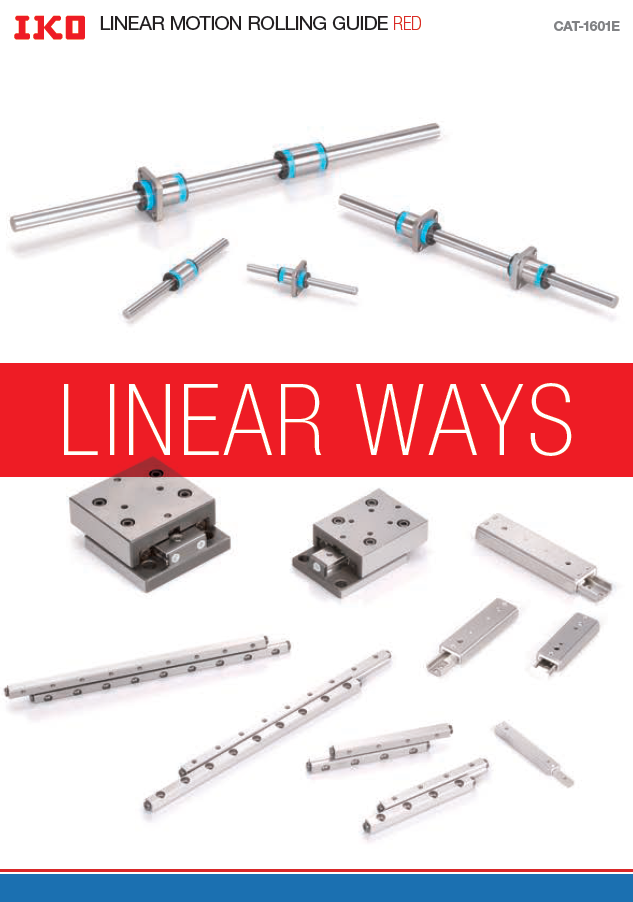
LLININEEAARR WWAAYYSS
• The sp•e Tchifeic saptieocnisfi caantdio dnism aennds idoinmse onfs pioronsd uocf tps riond tuhcists c iant athloisg caareta slougb jaercet stou bcjheacnt gtoe cwhiathnoguet wpirtihoor ut prior
RecognizRinegc otghnatiz icnogn sthearvt actions eorfv athtieo ng lofb athl ee ngvloirbonalm envt iriosn ment is
the top-pthrieo rittoyp c-phraiollerintyg ec hfoarll etnhgee w forl dth’se pwoopruldla’sti opno, pNuilpaption , Nippon notice. notice.
ThompsoTnh owmillp csoonnd wuciltl citos nadcuticvti titess awcittihvi tcieosn swiditehr actoionns idoef rtahteio n of the • When •t hWeshe np rtohdeusec tps raordeu ecxtsp oartee edx, pthoert exdp, othrtee er xsphorutledr csohnofuirlmd cao fnofrirwma rad finogrw caorudnintrgy caonudn atr yu saen,d a an du,s e, and,
environmenvt iraosn mae cnot rapso ra tec osropcoiraal tere spoocinasl ibreilsitpy,o nresdibuiclitey , itrse duce its in case i no fc fasllein go fu fnadlleinrg t huen dcuesr ttohme ecru's troemqueirr'esm reeqnutsir,e tmakeen tnse, ctaekses anreyc persoscaerdy uprreosc seudcuhre ass s euxcpho arts export
negative nimegpaatcivte oinm pthaec te onnvi rtohnem envt,ir oanmd ehnet,lp a nfods theer lpa froicshte r a rich
global engvliorobnaml envt.ironment. permisspioenrm apispsliiocna taiopnp.lication.
• Althou•g Ah ltahllo duagtha ainll tdhaista c iant athloisg chaatsa lboege hna csa brefeunll yc acroemfuplliyle cdo tmo pmileadke t oth me ainkfeo rtmhea tiniofon ramsa ctiomn palse tceo amsp lete as
possiblep,o NsIsPibPlOe,N N TIPHPOOMNP TSHOONM CPOS.O, LNT DC.O s.h, aLTll Dn.o st hbael l linaobtl eb efo lri aabnlye dfoarm aangye dsa wmhaagtesso ewvhear,t sdoirevcet ro, rd irect or
ISO 9IS00O1 9&0 0114 0&0 1 4Q0u0a1 liQtyu asylistyte smys tem indirect,i nbdaisrecdt ,u bpaosne dan uyp ionnfo armnya tiniofon rimn athtiiosn c iant athloisg .c NatIaPlPogO.N N TIPHPOOMNP TSHOONM CPOS.O, LNT DC.O m., aLkTeDs. nmoa kes no
regisrteragtiisotnra ctieornti ficcearttieficate warrantyw, aerirtahnetry e, xepitrheesrs e oxrp irmespsil eodr ,i minpcilluedi,n ign cthlued iimngp itlheed iwmaprirlaendt yw oarf rmanetryc hoaf nmtaebrcilhitayn otar bfiitlniteys osr ffoitrn ae ss for a
particulapra prtuicruploasr ep.urpose.
• Repro•d uRcetpiorno dauncdt icoonn avnedrs ci on vweirtshiount wpiethrmouists pioenrm arises piorno haibreit epdro.hibited.
CAT-1C6A0T1-E1601PErinted iPnr iCntheinda i n© C2h0in2a4 .©072 0(A2K4A.0)7 (AKA)
LINEAR MOTION ROLLING GUIDE RED
LINEAR MOTION ROLLING GUIDE RED
Page2
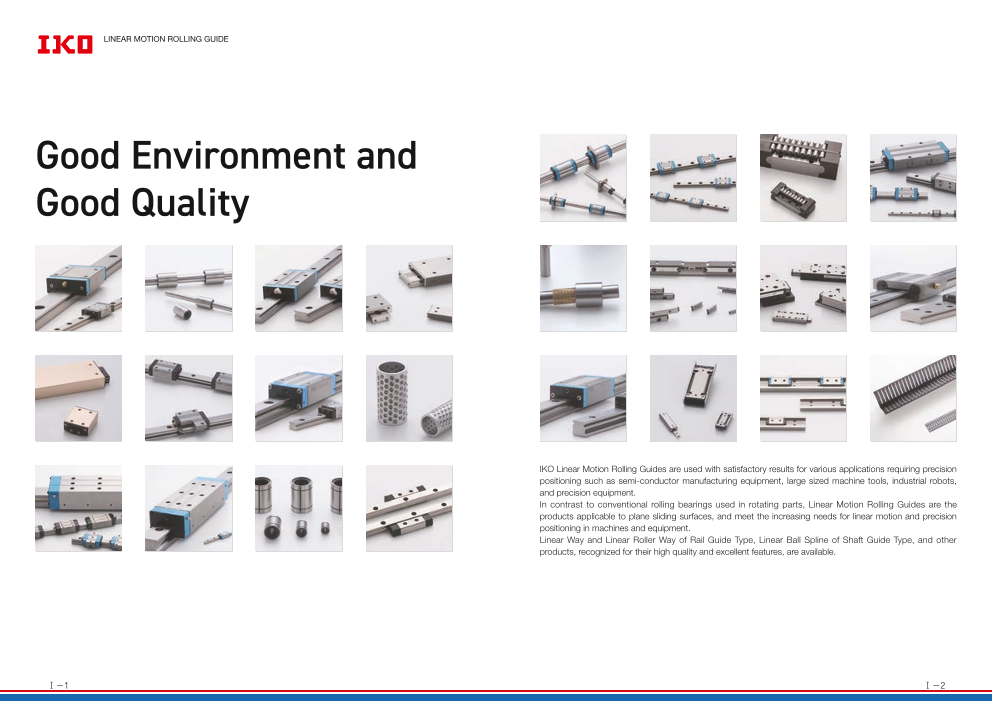
LINEAR MOTION ROLLING GUIDE
Good Environment and
Good Quality
IKO Linear Motion Rolling Guides are used with satisfactory results for various applications requiring precision
positioning such as semi-conductor manufacturing equipment, large sized machine tools, industrial robots,
and precision equipment.
In contrast to conventional rolling bearings used in rotating parts, Linear Motion Rolling Guides are the
products applicable to plane sliding surfaces, and meet the increasing needs for linear motion and precision
positioning in machines and equipment.
Linear Way and Linear Roller Way of Rail Guide Type, Linear Ball Spline of Shaft Guide Type, and other
products, recognized for their high quality and excellent features, are available.
Ⅰ-1 Ⅰ-2
Page3
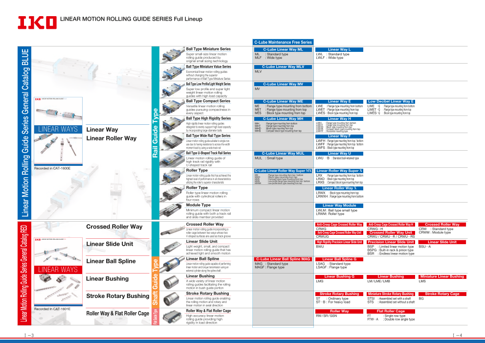
IKO Linear Motion Rolling Guide Series Full Lineup
LINEAR MOTION ROLLING GUIDE SERIES Full Lineup
C-Lube Maintenance Free Series
Ball Type Miniature Series C-Lube Linear Way ML Linear Way L
Super small-size linear motion ML : Standard type LWL : Standard type
rolling guide produced by MLF : Wide type LWLF : Wide type
original small sizing technology
Ball Type Miniature Value Series C-Lube Linear Way MLV
Economical linear motion rolling guides MLV
without changing the superior
performance of Ball Type Miniature Series
Ball Type Low Profile/Light Weight Series C-Lube Linear Way MV
Super low profile and super light MV
weight linear motion rolling
guides with high load capacity
LINEAR MOTION ROLLING GUIDE BLUE
Ball Type Compact Series C-Lube Linear Way ME Linear Way E Low Decibel Linear Way E
Versatile linear motion rolling ME : Flange type mounting from bottom LWE : Flange type mounting from bottom LWE …Q : Flange type mounting from bottom
guides pursuing compactness in MET : Flange type mounting from top LWET : Flange type mounting from top LWET …Q : Flange type mounting from top
every aspect MES : Block type mounting from top LWES : Block type mounting from top LWES …Q : Block type mounting from top
Ball Type High Rigidity Series C-Lube Linear Way MH Linear Way H
High rigidity linear motion rolling guides MH : Flange type mounting from bottom LWH : Flange type mounting from bottom
MHT : Flange type mounting from top LWHT : Flange type mounting from top
LINEAR WAYS designed to evenly support high load capacity
Linear Way MHD : Block type mounting from top LWHD : Block type mounting from top
by incorporating large-diameter balls LWHS : Compact block type mounting from top
MHS : Compact block type mounting from top LWHY : Horizontal mounting type
Linear Roller Way Ball Type Wide Rail Type Series Linear Way F
Linear motion rolling guide suitable to single-row LWFH : Flange type mounting from top / bottom
use due to having resistance to across-the-width LWFF : Flange type mounting from top / bottom
moment load by using a wide track rail LWFS : Block type mounting from top
• The specifications and dimensions of products in this catalog are subject to change without prior
• When these products are exported, the exporter should confirm a forwarding country and a use, and, Ball Type U-Shaped Track Rail Series C-Lube Linear Way MUL Linear Way U
in case of falling under the customer's requirements, take necessary procedures such as export
• Although all data in this catalog has been carefully compiled to make the information as complete as
possible, NIPPON THOMPSON CO., LTD. shall not be liable for any damages whatsoever, direct or
indirect, based upon any information in this catalog. NIPPON THOMPSON CO., LTD. makes no
warranty, either express or impiled, including the impiled warranty of merchantability or fitness for a Linear motion rolling guide of MUL : Small type LWU …B : Standard ball-retained type
• Reproduction and conversion without permission are prohibited.
CAT-1587E Printed in China © 2021.08 (AKA) high track rail rigidity with
U-shaped track rail
Recorded in CAT-1600E Roller Type C-Lube Linear Roller Way Super MX Linear Roller Way Super X
Linear motion rolling guide that has achieved the MX : Flange type mounting from top / bottom LRX : Flange type mounting from top / bottom
MXD : Block type mounting from top
highest level of performance in all characteristics MXS : Compact block type mounting from top LRXD : Block type mounting from top
utilizing the roller's superior characteristic MXN : Low profile flange type mounting from top / bottom
MXNS : Low profile block type mounting from top LRXS : Compact block type mounting from top
Roller Type Linear Roller Way X
Roller type linear motion rolling LRWX : Block type mounting from top
guide with cylindrical rollers in LRWXH : Flange type mounting from bottom
four-rows
Module Type Linear Way Module
Minimum compact linear motion LWLM : Ball type small type
rolling guide with both a track rail LRWM : Roller type
and slide member provided
Crossed Roller Way Crossed Roller Way Anti-Creep Cage Crossed Roller Way Anti-Creep Cage Crossed Roller Way H Crossed Roller Way
Linear motion rolling guide incorporating a CRWG CRWG···H CRW : Standard type
roller cage between two ways whose two Anti-Creep Cage Crossed Roller Way Unit Crossed Roller Way Unit CRWM : Module type
V-shaped surfaces are used as track groove CRWUG CRWU / CRWU…R / CRWU…RS
LINEAR MOTION ROLLING GUIDE RED
Linear Slide Unit Linear Slide Unit High Rigidity Precision Linear Slide Unit Precision Linear Slide Unit Linear Slide Unit
Light weight, small, and compact BWU BSP : Limited linear motion type BSU…A
linear motion rolling guide that has BSPG : Built-in rack & pinion type
achieved light and smooth motion BSR : Endless linear motion type
Linear Ball Spline Linear Ball Spline C-Lube Linear Ball Spline MAG Linear Ball Spline G Stroke Ball Spline
Linear motion rolling guide capable of performing MAG : Standard type LSAG : Standard type
LINEAR WAYS linear motion and torque transmission using an MAGF : Flange type LSAGF : Flange type
external cylinder along the spline shaft.
Linear Bushing Linear Bushing Linear Bushing G Linear Bushing Miniature Linear Bushing
A wide variety of linear motion LMG LM / LME / LMB LMS
rolling guides facilitating the rolling
motion in bush guide portion
• The specifications and dimensions of products in this catalog are subject to change without prior
• When these products are exported, the exporter should confirm a forwarding country and a use, and, Stroke Rotary Bushing
in case of falling under the customer's requirements, take necessary procedures such as export Stroke Rotary Bushing Miniature Stroke Rotary Bushing Stroke Rotary Cage
• Although all data in this catalog has been carefully compiled to make the information as complete as
possible, NIPPON THOMPSON CO., LTD. shall not be liable for any damages whatsoever, direct or
indirect, based upon any information in this catalog. NIPPON THOMPSON CO., LTD. makes no Stroke Rotary Bushing
warranty, either express or impiled, including the impiled warranty of merchantability or fitness for a Linear motion rolling guide enabling ST : Ordinary type STSI : Assembled set with a shaft BG
• Reproduction and conversion without permission are prohibited.
CAT-1588E Printed in China © 2021.09 (AKA) the rolling motion and rotary and ST…B : For heavy load STS : Assembled set without a shaft
linear motion in axial direction
Recorded in CAT-1601E
Roller Way & Flat Roller Cage Roller Way & Flat Roller Cage Roller Way Flat Roller Cage
High accuracy linear motion RW / SR / GSN FT : Single row type
rolling guide providing high FTW…A : Double row angle type
rigidity in load direction
Ⅰ-3 Ⅰ-4
Linear Motion Rolling Guide Series General Catalog RED Linear Motion Rolling Guide Series General Catalog BLUE
Flat Guide Type Shaft Guide Type Rail Guide Type
LINEAR MOTION ROLLING GUIDE BLUE LINEAR MOTION ROLLING GUIDE RED
Page4
Types of Specifications of Linear Motion Rolling Guides Series
LINEAR MOTION ROLLING GUIDE SERIES Classification and
features
Types of Linear Motion Rolling Guides Specifications of Linear Motion Rolling Guides
Endless linear motion Linear Way
Limited linear motion ● NC machine tool
● Precision working
Linear Way Crossed Roller Way machine BLUE
● Robot
Endless ● Transfer machine
Ball linear motion Complex load, medium to heavy load
The Rail Guide Type achieves linear
motion along a rail. This product can Linear Roller Way ● Heavy duty
receive a complex load and features machine tool
high performance, excellent total ● Large working
balance and easy handling. machine BLUE
Endless ● High-rigidity
Roller linear motion Complex load, heavy to extra-heavy load robot
Linear Roller Way Linear Slide Unit Crossed Roller Way ● Precision working
machine
● Electronic parts
assembling machine RED
Limited ● Precision measuring
Roller linear motion Complex load, medium load instrument
Linear Slide Unit
● Electronic parts
assembling
machine RED
Limited
Endless linear motion Limited linear motion + rotation Ball linear motion Complex load, light to medium load
Linear Ball Spline Stroke Rotary Bushing Linear Ball Spline ● Robot
● Testing and
The Shaft Guide Type achieves linear inspection
equipment RED
motion along a shaft. This product is
Endless ● Transfer
easy to handle and suitable for relatively Ball linear motion Complex load, medium to heavy load machine
low load conditions. Some shaft guide
products can achieve both rotation and Linear Bushing ● Packaging
reciprocating linear motion. machine
● Measuring
instrument RED
Linear Bushing Endless ● Medical
Ball linear motion Radial load, light load instrument
Stroke Rotary Bushing
● Printing press
● Press die set
● Precision RED
measuring
Limited linear instrument
Ball motion + rotation Radial load, light load
Roller Way
● NC machine
tool
The Flat Guide Type achieves linear Endless linear motion Limited linear motion ● Precision RED
motion on a surface. This product can working
receive only a unidirectional load but Roller Way Flat Roller Cage Endless machine
Roller linear motion Unidirectional load, extra-heavy load
feature high rigidity in the load direction.
Flat Roller Cage ● Precision
working
machine
● Optical RED
Limited measuring
Roller linear motion Unidirectional load, extra-heavy load instrument
Code description Excellent Good Fair
Ⅰ-5 Ⅰ-6
Flat Guide Type Shaft Guide Type Rail Guide Type
Guide Type
Flat Guide Type Shaft Guide Type Rail Guide Type
Limited Endless Limited
linear motion linear motion linear motion Endless linear motion Limited linear motion Endless linear motion+ rotation
Type of rolling
element
Type of
motion
Load
direction and
load carrying
capacity
Rigidity
Frictional
characteristic
Ease of
mounting
General
applications
Item-listed
catalog
Page5
Linear Motion Rolling Guide Series General Catalog RED INDEX
LINEAR MOTION ROLLING GUIDE SERIES RED INDEX
Crossed Roller Way Linear Bushing
CRWG CRWG…H CRW CRWM LMG LM LMS
Linear motion rolling guide incorporating a roller A wide variety of linear motion rolling guides
cage between two ways whose two V-shaped facilitating the rolling motion in bush guide portion
surfaces are used as track groove
Ⅱ-7 Ⅱ-133
Crossed Roller Way Unit Stroke Rotary Bushing
CRWUG CRWU ST STSI BG
A linear motion rolling guide with high rigidity table Linear motion rolling guide enabling the rolling
and bed incorporating CRWG and CRW guides for motion and rotary and linear motion in axial
excellent load balance. direction
Ⅱ-55 Ⅱ-175
High Rigidity Precision Linear Roller Way
Slide Unit RW SR GSN
BWU High accuracy linear motion rolling guide
Light weight, small, and compact linear motion providing high rigidity in load direction
rolling guide that has achieved light and smooth
motion
Ⅱ-75 Ⅱ-195
Precision Linear Slide Unit Flat Roller Cage
BSP BSPG BSR BSU FT FTW…A
Light weight, small, and compact linear motion High accuracy linear motion rolling guide
rolling guide that has achieved light and smooth providing high rigidity in load direction
motion
Ⅱ-83 Ⅱ-205
Linear Ball Spline
MAG LSAG
Linear motion rolling guide capable of performing
linear motion and torque transmission using an
external cylinder along the spline shaft.
Ⅱ-107
Ⅰ-7 Ⅰ-8
Page6
Table of contents
2011.04.13 再校 CAT-1553 目次_Ⅱ001-002
Explanation and Dimension Table for Respective Product Series
Rail Guide Type Linear Bushing
Crossed Roller Way ● Linear Bushing G
Explanation ···Ⅱ-133 Dimension Table
● ···Ⅱ-139
Anti-Creep Cage
Crossed Roller Way ● Linear Bushing
Anti-Creep Cage
Explanation ···Ⅱ-141 Dimension Table
Crossed Roller Way H ···Ⅱ-147
Crossed Roller Way ● Miniature Linear Bushing
Explanation ···Ⅱ-7 Dimension Table ···Ⅱ-27 Explanation ···Ⅱ-169 Dimension Table ···Ⅱ-172
● Anti-Creep Cage Stroke Rotary Bushing
Crossed Roller Way Unit
Crossed Roller Way Unit ● Stroke Rotary Bushing
Explanation ···Ⅱ-55 Dimension Table ···Ⅱ-61 Explanation ···Ⅱ-175 Dimension Table ···Ⅱ-179
Linear Slide Unit ● Miniature Stroke Rotary Bushing
Explanation ···Ⅱ-183 Dimension Table ···Ⅱ-187
● High Rigidity Precision Linear Slide Unit
Explanation ···Ⅱ-75 Dimension Table ···Ⅱ-81 ● Stroke Rotary Cage
Explanation ···Ⅱ-189 Dimension Table ···Ⅱ-192
● Precision Linear Slide Unit
Explanation ···Ⅱ-83 Dimension Table ···Ⅱ-89 Flat Guide Type
● Linear Slide Unit ● Roller Way
Explanation ···Ⅱ-95 Dimension Table ···Ⅱ-99 Explanation ···Ⅱ-195 Dimension Table ···Ⅱ201
Shaft Guide Type ● Flat Roller Cage
Explanation ···Ⅱ-205 Dimension Table ···Ⅱ-211
Linear Ball Spline
● C-Lube Linear Ball Spline MAG
Linear Ball Spline G
Explanation ···Ⅱ-107 Dimension Table ···Ⅱ-123
U.S. PATENTED
Crossed Roller Way Linear Ball Spline
No. 8360644 No. 6190046 5967667 General Explanation
8142079 6176617 5490729
6971797 6082899
6736541 Linear Bushing ● General Explanation ···················································································Ⅲ-2
Linear Slide Unit No. 6099410
No. 7344310 5893646
7008107
5553946
C-Lube Linear Ball Spline MAG Introduction of Application Examples
No. 7637662
● Introduction of Application Examples ······················································Ⅳ-1
Ⅱ-1 Ⅱ-2
Page7
Crossed Roller Way CRW(G)(…H) CRWU(G)
Crossed Roller Way
Anti-Creep Cage Crossed Roller Way
Anti-Creep Cage Crossed Roller Way H
Crossed Roller Way
Anti-Creep Cage Crossed Roller Way Unit
Crossed Roller Way Unit
Ⅱ-3 Ⅱ-4
Page8
Features of Crossed Roller Way Series
A wide variety of series products including cage misalignment prevention
mechanism are available! Features of Crossed Roller Way
IKO Crossed Roller Way is a linear motion rolling guide incorporating a roller cage be- Features of Built-in Rack & Pinion Type
tween two ways whose two V-shaped surfaces are used as track groove. Arrange-
ment of cylindrical rollers by orthogonalizing them alternately allows receiving of loads Solves Cage Creep Issue!
in any direction and executes extremely high-accuracy and smooth linear motion.
Perfect solution for cage creep issues
No cage creep even under high-tact operation in vertical axis
by a built-in rack and pinion mecha- !
Crossed Roller Way Crossed Roller Way Unit nism as an original design. 《Durability test》Test conditions
Model number CRWG3 CRWG
CRW·CRWM CRWU ■ Freedom in Mounting Test method Vibration test machine
This series is reliable for applications such as Posture Vertical
vertical axis where Crossed Roller Way may Maximum velocity 827 mm/s
have chances of cage creep. Acceleration 15 G
Condition
Number of cycle 31 Hz
■ Vibration
High-Speed and High-Tact Stroke length 8 mm machine
Operation Mass of moving part 330 g
Total cycles 100,000,000 cycles
Any corrective operation for cage creep is not
necessary even for high velocity operation. 《Result》 No cage creep nor material damage
in any component is found.
■ Saving Energy
No remedy motion of cage is necessary even in
long term operation.
Anti-Creep Cage Anti-Creep Cage
Crossed Roller Way Crossed Roller Way H Interchangeable in Mounting Dimensions!
CRWG CRWG···H Adoption of original structure of arrang- A A
ing a rack inside the way keeps the Rack
same mounting dimensions as conven-
Pinion gear
IKO Anti-Creep Cage Crossed Roller Way CRWG is a tional Crossed Roller Way CRW.
product with a cage creep IKO proof function using a CRWG CRW
rack and pinion mechanism originated from the * The mounting dimensions of CRWG1… CRWG···H
Crossed Roller Way CRW featuring smooth linear H and CRW1 are different.
A A
motion with super high accuracy. Rack
CRWG … H is high load capacity type of CRWG, ■ Easy Replacement Rack
which has achieved greatly increased load rating by
Pinion gear Rack Since they have the same external dimensions to
redesigning of raceway of CRWG. those of the existing Crossed Roller Way and Pinion gear
Original rack & pinion structure Crossed Roller Way Unit, existing Crossed Roller
Rack Way and Crossed Roller Way Unit can be replaced
Cylindrical rollers Pinion gear
Cage Roller cage without any mounting dimensions modification. CRWUG CRWU
Built-in rack & pinion type Smooth and Extremely-High Accurate Operation!
Solves cage creep issue!! Combination of precisely finished
raceways and non-recirculating type
linear motion rolling guide with super
high precision rollers provides superbly
Anti-Creep Cage smooth motion with very high accuracy.
Crossed Roller Way Unit
CRWUG ■ Improved Running Accuracy ■ Suitable for Micro-Feeding
Rack
Pinion gear Extremely high running accuracy can be achieved without Improvement of precision positioning accuracy and
IKO Anti-Creep Cage Crossed Roller Way Unit run deflection by recirculating type linear motion rolling superior corresponding feature to micro-feeding command
Cylindrical rollers guide. can be expected because of the linear motion without
CRWUG is a product with a cage creep proof Cage Roller cage stick-slip by extremely small frictional resistance.
function-provided Crossed Roller Way CRWG mounted
into a ground-finished rigid table and bed. Rack
CRWUG structure
1N=0.102kgf=0.2248lbs.
Ⅱ-5 1mm=0.03937inch Ⅱ-6
H
H
H
H
Page9
Anti-Creep Cage Identification Number and Specification
Crossed Roller Way Example of an identification number
The specifications of CRWG series, CRWG…H series, and
CRWG CRW series are indicated by the identification number.
Indicate the identification number, consisting of a model
code, a dimension, a part code, a material code, a
classification symbol, and any supplemental codes for each
specification to apply.
1 2 3 1 4 5 6 7
CRWG series
Pinion gear CRWG…H series CRWG 3 - 150 H SP /B
Rack CRW series Standard type CRW 3 - 150 C20 SL SP /U
Anti-Creep Cage CRW 3 - 250×300 C36 SL SP /U
Crossed Roller Way H
Module type CRWM 3 - 150 C20 SP
CRWG… Way
H CRWM 3 - 250×150 C20 SP
Way
Cylindrical rollers
Roller
cage cage 1 Model
Model
Page Ⅱ-9
code
End screw
Rack 2 Size
Dimensions Page Ⅱ-9
Crossed Roller Way
CRW/CRWM 3 Way length
Part
Page Ⅱ-10
code
4 Number of cylindrical rollers
Points 5 Material type
Material
Page Ⅱ-10
code
● Superior load balance ● Standard type and module type
This unit has a roller cage with cylindrical rollers There are two types in the CRW: one is standard type of 6 Accuracy class
1 Classification
alternately orthogonalized between two ways whose two 4using four ways and two roller cages in combination as a Page Ⅱ-11
symbol
V-shaped surfaces are used as track grooves, which set and the other is module type of integrating two
enables loads to be received in any direction. internal ways in a single structure.
● Solves cage creep problem ● Easy mounting 7 Special specification
Supplemental
Page Ⅱ-11
CRWG and CRWG…H units, which have The mounting holes of the way are provided with boring code
2originally-designed rack and pinion mechanism built-in, 5and female thread, so that the mounting structure is not Note: One set of the CRW, CRWG, and CRWG...H series consists of a combination of four ways and two roller cages.
solve the cage creep issue and support high-speed & restricted. The module type with two internal ways
high-tact operation and vertical axis application. integrated in a single structure is simple in mounting
structure, thus producing high accuracy linear motion.
● High load capacity type CRWG…H ● Stainless steels superior in corrosion
CRWG…H has achieved greatly increased load rating by resistance are listed on lineup.
3redesigning of raceway of CRWG, thereby downsizing the 6Products made of stainless steel are highly resistance to corrosion,
machine and equipment and prolonging their lifetime. so that they are suitable for applications where rust prevention oil is
not preferred, such as in a cleanroom environment.
1N=0.102kgf=0.2248lbs.
Ⅱ-7 1mm=0.03937inch Ⅱ-8
Page10
Identification Number and Specification -Model ・ Size- -Way length ・ Number of Cylindrical Rollers ・ Material Type-
1 Model Anti-Creep Cage Crossed Roller Way :CRWG 3 Way length ○ The way length is indicated in mm. The CRW
(CRWG series) ○×○ series can be combined with a way of
Anti-Creep Cage Crossed Roller Way H : CRWG…
different length. For details of way length, see
H
( the dimension tables on pages Ⅱ-27 to Ⅱ-52.
CRWG…H series)
Crossed Roller Way Standard type : CRW
(CRW series) Module type : CRWM
For applicable models and sizes, see Fig. 1. Specifying the combination of different way lengths
2 Size Combination of standard type Combination of module type
1, 2, 3, 4, 6, 9, 12, 15, 18, 24 For applicable models and sizes, see Table 1.
This combination consists of two short ways, two long This combination consists of one center way, two outside
ways, and two roller cages, as a set. ways, and two roller cages, as a set.
Table 1 Models and Sizes of CRWG series, CRWG…H series, and CRW series In this case, make sure to specify the number of rollers to be In this case, make sure to specify the number of rollers to be
Size incorporated in the roller cages. (For calculation of incorporated in the roller cages. (For calculation of
Series Shape Material Model incorporated rollers, see the Selection of CRW Series on incorporated rollers, see the Selection of CRW Series on
1 2 3 4 6 9 12 15 18 24
page Ⅱ-17.) page Ⅱ-17.)
High carbon
CRWG CRWG - ○ ○ ○ ○ - - - - -
steel made Example CRW 6 − 300 × 400 C24 Example CRWM 3 − 200 × 150 C20
High carbon The number of cylindrical rollers The number of cylindrical rollers
CRWG…H CRWG…H ○ ○ ○ ○ - - - - - -
steel made to be incorporated in a unit: 24 to be incorporated in a unit: 20
Length of long way: 400 mm Length of outside way: 150 mm
Length of short way: 300 mm Length of center way: 200 mm
High carbon
CRW ○ ○ ○ ○ ○ ○ ○ ○ ○ ○
Standard type steel made
Stainless steel
CRW…SL ○ ○ ○ ○ ○ - - - - -
CRW made
Module type
High carbon
CRWM ○ ○ ○ ○ - - - - - -
steel made
4 Number of cylindrical rollers :No symbol This represents the number of cylindrical rollers
:C○ incorporated into a CRW series cage. If not directed,
the number of cylindrical rollers indicated in the
dimension table shall be incorporated in a roller cage.
5 Material type High carbon steel made :No symbol For applicable models and sizes, see Fig. 1.
Stainless steel made :SL
1N=0.102kgf=0.2248lbs.
Ⅱ-9 1mm=0.03937inch Ⅱ-10
Page11
-Accuracy Class ・ Special Specification- -Special Specification-
6 Accuracy class Standard :No symbol For parallelism of the raceway to reference mounting Special mounting screw /B
Super precision :SP surface and the tolerance of the parallelism of two
raceways of CRWM, see Fig. 1. Preload adjusting-side way can be moved by adjusting the preload. Allowance for movement is required between a way
fixing screw and mounting hole, but special mounting screws are provided for the cases where enough allowance is not
provided or a fixing screw should be mounted from the way side as shown in Fig. 2.
This special mounting screw can also be used for the case where the mounting hole for mounting the fixed-side way and
Δ/L A Δ/L positioning accuracy of female thread are not enough. This special mounting screw is high carbon steel-made only.
Δ/L A Δ/L A
Table 4 Dimensions of special mounting screw
A
L H
B Δ/L B S
A
CRWG, CRWG…H, CRW CRWM
10
8 Bolt size
6 unit: mm
SP
4 Size Bolt size d D H L S
3 M 3 2.3 5 3 12 5
2
4 M 4 3.1 6 4 15 6
0 200 400 600 800 1000 1200 6 M 5 3.9 8 5 20 8
Fig. 2 Mounting by special mounting screw
Way length L mm 9 M 6 4.6 8.5 6 30 12
12 M 8 6.2 11.5 8 40 17
Fig. 1 Accuracy 15 M10 7.9 14 10 45 16
18 M12 9.6 16 12 50 19
24 M14 11.2 19.5 14 70 26
7 Special specification B, M, SA, SB, U For applicable special specifications, see Table 2.
For combination of multiple special specifications, see Table 3. High rigidity roller cage /M
For details of special specifications, see pages Ⅱ-11 to Ⅱ-14.
The cage is changed into a high rigidity copper alloy-made cage
designed to suit vertical axis application. This cage has a structure
to prevent a roller from dropping off in one-side direction.
For using a high rigidity roller cage for vertical axis application, it is
Table 2 Application of special specifications recommended to use the cage in combination with end stopper SB.
Supplemental Size
Special specification
code 1 2 3 4 6 9 12 15 18 24
Special mounting screw /B - - ○ ○ ○ ○ ○ ○ ○ ○
High rigidity roller cage( 1) /M - - - - ○ ○ ○ ○ ○ ○
End stopper SA( 1) /SA - ○ ○ ○ ○ ○ ○ ○ ○ ○
End stopper SB( 1) /SB - ○ ○ ○ ○ ○ ○ ○ ○ ○
Wiper seal( 1) /U - ○ ○ ○ ○ ○ ○ ○ ○ ○
Notes(1) Applicable only to CRW series standard type. Not applicable to other series or shapes.
Table 3 Combination of special specifications
M ○
SA ○ ○
SB ○ ○ -
U ○ ○ - -
B M SA SB
Remarks 1. The combination of "-" shown in the table is not available.
2. When using multiple types for combination, please indicate by arranging the symbols in alphabetical order.
1N=0.102kgf=0.2248lbs.
Ⅱ-11 1mm=0.03937inch Ⅱ-12
Parallelism Δ μm
d
D
Page12
-Special Specification- -Special Specification-
End stopper SA /SA Wiper seal /U
When the stroke frequency is high and cage creep may be caused by the vibration and non-uniformly varying load, the In order to prevent foreign substances from entering into a raceway, the wiper seal is changed into the one with a function
end screw is changed into end stopper SA. of end stopper SB.
For the series of size 1, an end stopper SA according to end stopper SA is included as standard. The wiper seal cannot be mounted on all way ends. Standard mounting positions are shown in Fig. 4. The mounting
positions can be changed by loosening the screw.
Table 5 Dimensions of end stopper SA
Table 7 Dimensions of wiper seal
t1
t2 t1
t2
unit: mm
Size t1 t2 Size t1 t2 unit: mm
2 4.5 2 12 11 5 Size t1 t2 Size t1 t2
3 5 2 15 14 6 2 4.5 4 12 11 8.5
4 7 3 18 14 6 3 5 4 15 14 11
6 8 3 24 16 6 4 7 6 18 14 11
9 10 4 6 8 6 24 16 11 Fig. 4 Arrangement of wiper seal
9 10 7.5
End stopper SB /SB
When using a high rigidity roller cage for vertical axis application, the end screw is changed into end stopper SB to
regulate the cage stroke at the end.
The end stopper SB cannot be mounted on all way ends. Standard mounting positions are shown in Fig. 3. The mounting
positions can be changed by loosening the screw.
Table 6 Dimensions of end stopper SB
t1
t2
unit: mm
Size t1 t2 Size t1 t2
2 4.5 2 12 11 5
3 5 2 15 14 6
4 7 3 18 14 6
6 8 3 24 16 6 Fig. 3 Arrangement of end stopper SB
9 10 4
1N=0.102kgf=0.2248lbs.
Ⅱ-13 1mm=0.03937inch Ⅱ-14
Page13
Load Rating and Allowable Load
Basic dynamic load rating C, basic static load rating C0, and allowable load F Table 8.2 Calculating formula of load rating and allowable load of module type CRW series
of the CRWG series and CRWG…H series show values for downward loads Upward and downward load Lateral load
in case of parallel arrangement of four ways and two pairs of roller cages as C, C0, F
one set. (Refer to Fig. 5) In addition, the upward and lateral load rating is the 1/2 of the load 1/2 of the load
same as downward load rating.
For the CRW series, since the number of cylindrical rollers that share load of Load direction Load Load
each direction varies, the load rating for each load direction and allowable
load must be obtained. In addition, basic dynamic load rating CU, basic static
Load
load rating C0U, and allowable load FU in the dimension table show values per
cylindrical roller. Fig. 5 Direction of load rating of the CRWG series and 1/36 3/4 7/9 1/36 3/4
=
Basic dynamic load rating C, basic static load rating C dynamic load rating C N C {(―Z2-1)2p} (―Z2 ) 2 C (7) C ={(―Z- 2p Z 7/9
C (10)
U a 2 1) } (―2 ) 2
U
0, and allowable load F Basic
CRWG…H series r
of the CRW series are obtained based on the equation indicated in Table 8.1
and Table 8.2. Basic static load rating C N C =2 ―Z0 2 )C (8) C =2
0r ( 0U 0a (―Z2 )C (11)
0U
For more information on the definition of load rating and calculated load, see
page Ⅲ-3. Allowable load F N F=2 ― ) F =2 )
r (Z
2 )F (9
U a (―Z2 )F (12
U
Allowable load Cr:Basic dynamic load rating in case upward and downward load is applied N
Ca:Basic dynamic load rating in case lateral load is applied N
Allowable load refers to load of smooth rolling motion on contact surface to C0r:Basic static load rating in case upward and downward load is applied N
which maximum contact stress is applied and the sum of whose elastic C0a:Basic static load rating in case lateral load is applied N
deformation of rolling elements and raceway is small. Fr:Allowable load in case upward and downward load is applied N
Therefore, use applied load within the allowable load range if very smooth Fa:Allowable load in case lateral load is applied N
rolling motion and high accuracy are required. Code description
The number of cylindrical rollers incorporated in a roller cage
Z:
(omit the figures after the decimal fractions for ―Z2 )
p:Inter-pitch dimensions of cylindrical rollers mm
Table 8.1 Calculating formula of load rating and allowable load of standard type CRW series
CU:Basic dynamic load rating per cylindrical roller N
Upward and downward load( 1) Lateral load C0U:Basic static load rating per cylindrical roller N
Load FU:Allowable load per cylindrical roller N
Load direction Load Load
Load
Basic dynamic load rating /36 3/4 7/9
C N 1/3 3/4
C={(―Z
6
2-1)2p} (―Z2 ) C (1) C ={(―Z
1
-1)2p} (―Z2 ) 2 C (4)
r U a 2 U
Basic static load rating C0 N C = ―Z2 )C (2) C =2 ―Z 5)
0r ( 0U 0a ( 2 )C (
0U
Allowable load F N F= ―Z (3) F =2 ―Z
r ( 2 )F 2 )F (6)
U a ( U
Cr:Basic dynamic load rating in case upward and downward load is applied N
Ca:Basic dynamic load rating in case lateral load is applied N
C0r:Basic static load rating in case upward and downward load is applied N
C0a:Basic static load rating in case lateral load is applied N
Fr:Allowable load in case upward and downward load is applied N
F
e description a:Allowable load in case lateral load is applied N
Cod
The number of cylindrical rollers incorporated in a roller cage
Z:(omit the figures after the decimal fractions for ―Z2 )
p:Inter-pitch dimensions of cylindrical rollers mm
CU:Basic dynamic load rating per cylindrical roller N
C0U:Basic static load rating per cylindrical roller N
FU:Allowable load per cylindrical roller N
Note( 1): In case of parallel arrangement in this load direction, calculation must be performed based on the equations( 7),( 8), and( 9) in
Table 8.2.
1N=0.102kgf=0.2248lbs.
Ⅱ-15 1mm=0.03937inch Ⅱ-16
Page14
Selection of CRW Series
For selection of CRW series specifications, stroke length ❸ Calculation of cage length and the number of rollers (2) For Size 1 series Calculation examples
and the number of cylindrical rollers, as well as accuracy, With the way length and maximum stroke length determined, The stroke length is regulated by cage and end stopper and
load rating and allowable load, must be determined. the allowable length for cage can be calculated. the cage length is obtained by the following equation. Form of use ………………………………………… CRW 6
Calculation method of the cage length varies depending on Applied load ………………………………………… P = 7000 N
Stroke length and the number of cylindrical rollers specifications of end screws and end stopper fitted to the R=L- S1 (17) Stroke length ………………………………………… S = 195 mm
2
way end.
Stroke length of the CRW series affects the way length and Where R: Allowable cage length mm Select specifications for parallel use of Crossed Roller Way
the number of cylindrical rollers. (1) With standard end screws and end stopper SA (excluding Size 1 series) L: Way length mm under the above conditions (refer to Fig. 26 in page Ⅱ-23).
Therefore, select specifications by following the procedure The dimensions between rollers at both ends is obtained from S1: Maximum stroke length mm
below taking into account the stroke length used and the following equation by using a value obtained by subtracting ❶ Calculation of way length
applied load. a half of the maximum stroke length from the way length. The way length L is calculated from the equation (13).
L S1
S1/2❶ Calculation of way length LR=L- S1 (15) L≧1.5S=1.5×195=292.5
2
The way length, which should be 1.5 times longer than the
stroke length used, is obtained from the equation below. Where LR : Allowable dimensions between rollers at both Therefore, select L = 300 mm based on the standard length
ends mm in the dimension table.
L≧1.5S (13) L : Way length mm
R S1/2
S1 : Maximum stroke length mm ❷ Calculation of maximum stroke length
L
Where L: Way length mm The maximum stroke length S1 is calculated from the
S: Stroke length used mm equation( 14).
L S1 The number of rollers to be incorporated in a roller cage is
S1/2 obtained by the following equation. S1≧
1
S= 1 ×195≒244
S 0.8 0.8
Z= R-2e +1 (18) Allowable dimensions between rollers at both ends LR is
p
calculated from the equation (15).
Where Z : Number of cylindrical rollers (figures after the
LR S1/2 decimal fractions are omitted) LR= L- S1 =300- 244 =178
2 2
L≧1.5S L R: Allowable cage length mm
e : End dimension of cage (refer to the dimension ❸ Calculation of the number of rollers
table) mm The number of cylindrical rollers Z is calculated from the
❷ Calculation of maximum stroke length The number of rollers to be incorporated in a roller cage is p : Inter-pitch dimensions of cylindrical rollers (refer equation (16). However, DW and p in this form are
Ideally the stroke length used should be less than 80% of obtained by the following equation. to the dimension table) mm DW = 6 mm、p = 9 mm according to the dimension table.
the maximum stroke length, which is obtained from the
equation below. Z= LR-DW +1 (16) Z= LR-(3) For end stopper SB and wiper seal DW +1=178-6+1≒20.1
p p 9
The stroke length is regulated by cage and end stopper or
S1≧
1 S (14) Where Z : Number of cylindrical rollers (figures after the wiper seal and the cage length is obtained by the following Therefore, it should be Z = 20 by omitting figures after the
0.8
decimal fractions are omitted) equation. decimal fractions.
Where S1: Maximum stroke length mm LR : Allowed dimensions between rollers at both
S : Stroke length used mm ends mm R=L-t2-S1 (19) ❹ Calculation of allowable load
DW: Diameter of cylindrical rollers (refer to the Allowable load in parallel arrangement F is calculated from
dimension table) mm Where R : Allowable cage length mm equation (9) described in Table 8.2 in page Ⅱ-16. However,
p : Inter-pitch dimensions of cylindrical rollers L : Way length mm allowable load per cylindrical roller FU is FU = 769 N
(refer to the dimension table) mm S1 : Maximum stroke length mm according to the dimension table.
t2 : Thickness of end stopper SB or wiper seal mm
F=2(―Z(See Table 6 in page Ⅱ-13, and Table 7 in page 2 )F =2 2―0 1
U ( 2 )×769= 5380
Ⅱ-14) Therefore, allowable load F is larger than applied load P =
7000 N. When allowable load becomes smaller than applied
load, it is necessary to increase the number of cylindrical
rollers by extending way length, or increase the cylindrical
roller diameter.
R S t
1 2 ❺ Determination of specifications
L Specifications obtained in accordance with the above is
CRW6-300 and the number of cylindrical rollers is 20.
The number of rollers to be incorporated in a roller cage is
obtained by the equation (18) as with the Size 1 series.
1N=0.102kgf=0.2248lbs.
Ⅱ-17 1mm=0.03937inch Ⅱ-18
Page15
Lubrication Precaution for Use
Grease is not pre-packed in the CRWG series, CRWG…H ❶ Handling Table 9 Accuracy of mounting part
series and CRW series, so please perform adequate As the CRWG series, CRWG…H series and CRW series are ・Directly affects running accuracy.
lubrication as needed. designed highly precisely, take extra care for handling. For the flatness of two mounting surfaces
Accuracy of A
Both of oil lubrication and grease lubrication are available in A pinion gear and cylindrical roller are incorporated with the on table and bed sides, allowable value
surface
the CRWG series, CRWG…H series and CRW series. cage for the CRWG series and CRWG…H series. When the approximate to the parallelism indicated
in Fig. 1 in page Ⅱ-11 is recommended.
Generally, oil lubrication should be selected for high speed or cage is dropped or handled roughly, the pinion gear and
low frictional resistance, and grease lubrication for low speed. cylindrical roller may come off. Especially for CRWG…H, ・Flatness
For grease lubrication, use of high-quality lithium-soap base grabbing the cylindrical roller may take it off, so be sure to Affects preload (refer to ❹ Preload
adjustment mechanism).
grease is recommended. For light load and low speed, apply hold the cage body for handling. In addition, do not cut off Ⅱ-11Allowable value approximate to the
grease or oil to raceway, rack and pinion gear first and then the cage as doing so may cause pinion gear coming off and parallelism indicated in Fig. 1 in page Ⅱ
Accuracy of B Fig. 12 Example of push plate
reapply accordingly. However, the structure as indicated in breakage of gear joint section. -11 is recommended.
and C surfaces
the Fig. 6 allows for easy reapplication. In addition, since the A rack is incorporated with the way for the CRWG series ・Squareness
clearance between ways is small for CRWG…H series, apply and CRWG…H series. In operation, take note that the rack Affects rigidity in preload direction of the
mounting part of the CRWG series,
grease or oil directly to raceway for re-greasing. may come off when the end screw is removed. CRWG…H series and CRW series.
Though the cage for the CRW series may cut off to Process to sufficiently high accuracy.
necessary length, handle it with care not to deform it when
cutting.
❸ Shape of mounting part
❷ Accuracy of mounting part For the opposite corner of the mating reference mounting, it is
Examples of typical mounting surface processing are shown recommended to have relieved fillet as indicated in Fig. 10.
in Fig. 9.1 and Fig. 9.2. In addition, a clearance of 0.5 mm or higher should be made
General processing accuracy of mounting surface is between the way and the mating member material. Fig. 13 Example of tapered jib
according to Table 9. However, care should be exercised as
mounting surface accuracy directly affects running accuracy.
Fig. 6 Example of lubrication system Especially when high running accuracy is required, the ❺ Operating temperature
processing accuracy higher than that indicated in Table 9 is As synthetic resin components are used for the CRWG
required. series and CRWG…H series, the maximum operating
Dust Protection temperature is 120°C, while it should be lower than 100°C
for continuous use. When it exceeds 100°C, contact IKO.
As synthetic resin components are not used for the CRW
Since the CRWG series, CRWG…H series and CRW series series, it may be used at high temperature. However, when it
are finished with high accuracy, harmful foreign substances exceeds 100°C, contact IKO.
such as dust and particles entering into the bearing will cause C A A
low life or impaired accuracy. To prevent harmful foreign A B B Fig. 10 Shape of mounting part
A ❻ Maximum velocity
substances such as dust, particles and water from outside Operating velocity should be lower than 50 m/min for the
from entering, it is recommended to attach non-contact type ❹ Preload adjustment mechanism CRWG series and CRWG…H series, and lower than 30 m/
labyrinth seal as indicated in Fig. 7, or contact type wiper seal For use with preload, use the preload adjusting screw as min for the CRW series.
as indicated in the Fig. 8 to both sides. indicated in Fig. 11 as a general way. Preload adjusting
Fig. 9.1 Example of processing of CRWG, screw nominal dimensions and mounting position should be ❼ Tightening torque for fixing screw
CRWG…H and CRW mounting surface in accordance with the way fixing bolt dimensions and Typical tightening torque for mounting of the CRWG series,
position. Press the center of the way H dimensions. CRWG…H series and CRW series is indicated in Table 10.
Preload amount varies depending on operational conditions When vibration and shock are large or moment load is
of your machine and device. However, as excessive preload applied, it is recommended to fix by using the torque 1.3
may lead to short life and damage on the raceway, it is times larger than that indicated in the table. In addition,
typically ideal to adjust to zero clearance or slight preload when high running accuracy is required with no vibration
A state. When accuracy and rigidity are required, use a push and shock, it may be fixed by using torque smaller than that
C A plate or tapered jib as indicated in Fig. 12 and Fig. 13, indicated in the table, however, it is recommended to use
respectively. adhesive agent to fasten the screw, or to use stop bolts.
Fig. 7 Example of labyrinth seal
Table 10 Tightening torque for fixing screw
Tightening torque N・m Remark:
Fig. 9.2 Example of processing of CRWM mounting Bolt size
High carbon steel-made screw Stainless steel-made screw When fixing screws
surface M 1.6×0.35 0.20 - used on the table
M 2 ×0.4 0.40 0.31 side and bed side
are not identical,
M 3 ×0.5 1.4 1.1
fasten them all to
M 4 ×0.7 3.2 2.5 the smaller
M 5 ×0.8 6.4 5.0 tightening torque.
M 6 ×1 10.9 8.5
M 8 ×1.25 26.1 -
Fig. 11 Example of typical preload adjustment M10 ×1.5 51.1 -
M12 ×1.75 88.2 -
Fig. 8 Example of wiper seal M14 ×2 140 -
M16 ×2 215 -
1N=0.102kgf=0.2248lbs.
Ⅱ-19 1mm=0.03937inch Ⅱ-20
0.5 or higher
0.5 or higher
Page16
Mounting
Mounting of standard type CRW series, ❸ Mounting of bed-side way ・Position the table-side way in the stroke end position. ・Temporarily tighten the table fixing screws. (Refer to Fig. 22)
CRWG series, and CRWG…H series ・Properly align the way with mounting surface and (Refer to Fig. 19) ・While tightly pressing the fixing-side way to C surface
temporarily tighten fixing screws evenly to the tightening ・For CRWG and CRWG…H series, mate the pinion gear at (refer to Fig. 15), fully tighten the screws to the specified
Typical mounting structure is shown in Fig. 14. For mounting torque. the center of the cage and the rack of the table-side way. torque.
at this point, generally follow the procedure below. ・While making the way sticking to B surface (refer to Fig. 15)
tight, fully tighten the screws to the specified torque.
・When high running accuracy is required, fully and evenly
Preload-adjustment- tighten them to the specified torque while checking the
side way
Fixing-side way Bed-side way Bed-side way parallelism of the raceway along the full length of the way.
・Typical tightening torque for fixing screw is according to
Table 10 in page Ⅱ-20.
Preload
adjusting Δ
screw
Δ A Δ A
Fig. 14 Mounting example of standard type CRW series, CRWG, and CRWG…H
C surface
❶ Preparation for mounting Fig. 19
・Products are packed by set (4 ways and 2 pairs of roller A
cages). Be careful not to mix with other sets.
・Clean each part with clean wash fluid and then apply rust ・Position the table-side way approximately in the stroke Fig. 22
Fig. 16 Accuracy of way mounting
prevention and lubrication oil. To clean further, remove the center position. (Refer to Fig. 20)
end screw first. ・Fully stroke the table softly and check that it is within the
stroke range used and cylindrical rollers on both ends of
❷ Cleanup of mounting surface the cage do not contact with end screws of the way. If
・Remove burrs and blemishes on the machine mounting they make contact, take the procedure again. (Refer to
surface with an oil-stone, etc. Be careful about corner Fig. 23)
groove on the mounting surface, too.
・Wipe off dust and dirt with clean cloth and apply rust
prevention and lubrication oil lightly.
Corner groove Corner groove
Fig. 20
Mounting surface C Mounting surface A Mounting surface A Fig. 17
Mounting surface B Mounting surface B ❹ Operation of table and bed ・Position the table while holding the way to prevent it from
Mounting surface A Mounting surface A ・Position the roller cages at the stroke end positions of the moving. (Refer to Fig. 21)
bed-side way. (Refer to Fig. 18)
・For CRWG and CRWG…H series, mate the pinion gear at
the center of the cage and the rack of the way.
Corner groove ・At this point, be careful not to deform the cage. Fig. 23
Fig. 15 Mounting surface
Fig. 21
Fig. 18
1N=0.102kgf=0.2248lbs.
Ⅱ-21 1mm=0.03937inch Ⅱ-22
Page17
Mounting
❺ Preload adjustment ❸ nting of bed-side way ❺ Operation of table and bed
・Preload adjustment is performed with fixing screws of the High-accuracy mounting of standard Mou
・ h mounting surface and ・Make alignment of the position in height and cross
table-side way tightened temporarily. type CRW series Properly align the way wit
temporarily tighten fixing screws evenly to the tightening direction so that the roller cage can be inserted between
・Preload adjustment is started from the preload adjusting torque. the table-side way and bed-side way.
screw at the center of way length and then both ends in Typical mounting structure is shown in Fig. 26. For mounting ・While making the way sticking to B surface (refer to Fig. ・Carefully insert the roller cage and assembly it at
turn. at this point, generally follow the procedure below. 27) tight, fully tighten the screws to the specified torque. approximate center of the way length. At this point, be
・While measuring the clearance on the table sides, tighten ・When high running accuracy is required, fully and evenly careful not to deform the cage.
the preload adjusting screws subsequently until deflection tighten them to the specified torque while checking the ・Mount end screws and end stopper of each way.
of the dial gauge stops. Measure the tightening torque for Preload-adjustment- parallelism of the raceway along the full length of the way. ・Push the entire table against the preload adjusting screws
side way
preload adjusting screws at this point. Fixing-side way Bed-side way Bed-side way ・Typical tightening torque for fixing screw is according to and tighten the preload adjusting screws to make
・When adjusting preload adjusting screw near either end, Table 10 in page Ⅱ-20. temporary adjustment until the clearance between ways
stroke the table softly and check that the cylindrical roller becomes zero.
is on the preload adjusting screw section. ・Fully stroke the table softly and correct the roller cage
・After the above procedure, the clearance becomes zero or Δ
Preload position to the center.
in slight preload state, but preload is still not adjusted adjusting
screw Δ A Δ A
evenly. With the same procedure again, re-adjust all the
preload adjusting screws evenly to the torque previously
measured. Fig. 26 Mounting example of standard type CRW series
❶ Preparation for mounting A
・Products are packed by set (4 ways and 2 pairs of roller
Fig. 28 Accuracy of way mounting
cages). Be careful not to mix with other sets.
・Clean each part with clean wash fluid and then apply rust
prevention and lubrication oil. To clean further, remove the ❹ Mounting of table-side way
Fig. 30 Position alignment before operation
end screw first. ・Properly align the fixing-side way with mounting surface
and temporarily tighten fixing screws evenly to the
❷ Cleanup of mounting surface tightening torque. ❻ Preload adjustment
・Remove burrs and blemishes on the machine mounting ・While making the fixing-side way sticking to C surface ・Preload adjustment is performed with fixing screws of the
Fig. 24 Example of preload adjustment method
surface with an oil-stone, etc. Be careful about corner tight, fully tighten the screws to the specified torque. preload-adjusting-side way tightened temporarily.
groove on the mounting surface, too. ・Set back the preload adjusting screws in advance, make ・Preload adjustment is started from the preload adjusting
❻ Full tightening of preload-adjustment-side way ・Wipe off dust and dirt with clean cloth and apply rust the preload-adjusting-side way sticking to the mounting screw at the center of way length and then both ends in
・Fixing screws are lightly tightened to even torque. As with prevention and lubrication oil lightly. surface, and then temporarily tighten fixing screws lightly turn.
preload adjusting screws, temporarily fix them to torque to the even torque. ・While measuring the clearance on the table sides, tighten
similar to the specified torque in turn from the way center the preload adjusting screws subsequently until deflection
to both ends. Corner groove Corner groove of the dial gauge stops. Measure the tightening torque for
・When tightening fixing screws near either end, stroke the preload adjusting screws at this point.
table softly and check that the cylindrical roller is on fixing Fixing-side way ・When adjusting preload adjusting screw near either end,
C surface Preload-adjustment-side way
screw section. stroke the table softly and check that the cylindrical roller
・Finally with the same procedure, fully tighten all the fixing is on the preload adjusting screw section.
screws evenly to the specified torque. Mounting surface C Mounting surface A Mounting surface A ・After the above procedure, the clearance becomes zero or
in slight preload state, but preload is still not adjusted
❼ Check after assembly Preload adjusting screw
Mounting surface B Mounting surface B evenly. With the same procedure again, re-adjust all the
・Fully stroke the table softly and check that running is Mounting surface A Mounting surface A preload adjusting screws evenly to the torque previously
smooth without abnormal noise. measured.
・Measure the table upper and side surfaces with dial gauge
Fig. 29 Mounting of table-side way
or the like and check the running accuracy.
Corner groove
Fig. 27 Mounting surface
Fig. 31 Example of preload adjustment method
Fig. 25 Accuracy check after assembly
1N=0.102kgf=0.2248lbs.
Ⅱ-23 1mm=0.03937inch Ⅱ-24
Page18
Mounting
❼ Full tightening of preload-adjustment-side way Mounting of module type CRW series ❹ Processing of dowel pin hole Mating marks module type CRW series
・Fixing screws are lightly tightened to even torque. As with ・When dowel pins are used, machine holes on the bed in
preload adjusting screws, temporarily fix them to torque Typical mounting structure of CRWM is shown in Fig. 33. alignment with dowel pin holes near either end of the CRWM has mating marks to ensure the best running
similar to the specified torque in turn from the way center For mounting at this point, generally follow the procedure center way. accuracy after mounting based on the paral le l ism
to both ends. below. ・Dowel pin hole of the center way is finished for H7. Finish measurement result of reference mounting surface and
・When tightening fixing screws near either end, stroke the bed holes in the same way. raceway. When assembling the ways, align the mating marks
table softly and check that the cylindrical roller is on fixing ・Diameter and its allowance of dowel pin hole of the center of ways with the same end side as indicated in Fig. 36.
screw section. way vary depending on the dimension table.
Preload-adjustment-
・Finally with the same procedure, fully tighten all the fixing side way ・Eliminate cutting chips and clean up again as necessary.
screws evenly to the specified torque. Fixing-side way Center way When machines for mounting of the center way are large, Center way
clean them up with the center way removed and then Mating mark
❽ Check after assembly reassemble.
・Fully stroke the table softly and check that running is ・Load the dowel pins and check the parallelism of the
smooth without abnormal noise. Preload reference surface of the running parallelism and the
adjusting
・Measure the table upper and side surfaces with dial gauge screw raceway of the center way again.
or the like and check the running accuracy.
Fig. 33 Example of mounting of CRWM Mating mark
Fig. 36 Mating marks of CRWM
❶ Preparation for mounting
・Crossed Roller Way CRWM is packed by set (1 center
way, 2 ways and 2 pairs of roller cages). Be careful not to
mix with other sets.
・Remove end screws and end stopper, clean up each part
Fig. 32 Accuracy check after assembly with clean wash fluid and then apply rust prevention and
lubrication oil.
❷ Cleanup of mounting surface
・Remove burrs and blemishes on the machine mounting Fig. 35 Machining of dowel pin hole
surface with an oil-stone, etc. Be careful about corner
groove on the mounting surface, too.
・Rust prevention and lubrication oil should be applied after ❺ Operation of table and bed
cleaning each part with clean wash fluid. Remove end ・Complies with mounting of standard type CRW series,
screws and end stopper i f addit ional cleaning is CRWG series, and CRWG…H series.
necessary.
❻ Preload adjustment
❸ Mounting of center way ・Complies with mounting of standard type CRW series,
・Roughly align the center way to the mounting surface and CRWG series, and CRWG…H series.
lightly fix it with fixing screws.
・While measuring mounting parallelism of the center way ❼ Full tightening of preload-adjustment-side way
and raceway to the reference surface of running ・Complies with mounting of standard type CRW series,
parallelism for position correction, temporarily tighten the CRWG series, and CRWG…H series.
fixing screws to the even tightening torque.
・Evenly tighten all the fixing screws to the specified ❽ Check after assembly
tightening torque. ・Complies with mounting of standard type CRW series,
CRWG series, and CRWG…H series.
Running parallelism reference surface
Fig. 34 Mounting accuracy check for center way
1N=0.102kgf=0.2248lbs.
Ⅱ-25 1mm=0.03937inch Ⅱ-26
Page19
Anti-Creep Cage Crossed Roller Way
CRWG
Shape
Size 2 3 4 6 L
t E n×F E t
F H
R
e p Z (Number of rollers)
D
W
h
M
Mass (Ref.) Nominal dimensions mm Maximum Basic dynamic Basic static Allowable
stroke length load rating load rating load
Identification number Way( 1) Roller cage( 2) Boundary dimensions Dimension of roller cage Mounting dimensions C(3) C(3
0 ) F(3)
g g A H L(n×F) E DW R Z p e W g M d1 d2 h t mm N N N
CRWG 2- 30 6.53 0.38 30(1×15) 25.6 4 9 913 1 180 392
CRWG 2- 45 9.53 0.72 45(2×15) 41.6 8 7 1 570 2 350 783
CRWG 2- 60 12.5 0.88 60(3×15) 49.6 10 21 1 860 2 940 979
CRWG 2- 75 15.5 1.22 75(4×15) 65.6 14 19 2 420 4 110 1 370
CRWG 2- 90 18.5 1.39 12 6 90(5×15) 7.5 2 73.6 16 4 2.8 5.5 2.5 M3 2.55 4.4 2 1.5 33 2 680 4 700 1 570
CRWG 2-105 21.5 1.72 105(6×15) 89.6 20 31 3 190 5 880 1 960
CRWG 2-120 24.5 1.89 120(7×15) 97.6 22 45 3 440 6 460 2 150
CRWG 2-135 27.5 2.22 135(8×15) 113.6 26 43 3 910 7 640 2 550
CRWG 2-150 30.5 2.39 150(9×15) 121.6 28 57 4 150 8 230 2 740
CRWG 3- 50 22.8 1.69 50(1×25) 42 6 13 2 740 3 660 1 220
CRWG 3- 75 33.3 2.71 75(2×25) 62 10 23 4 080 6 090 2 030
CRWG 3-100 43.8 3.72 100(3×25) 82 14 33 5 300 8 530 2 840
CRWG 3-125 54.4 4.74 125(4×25) 102 18 43 6 440 11 000 3 660
CRWG 3-150 64.9 5.75 18 8 150(5×25) 12.5 3 122 22 5 3.5 8.3 3.5 M4 3.3 6 3.1 2 53 7 530 13 400 4 470
CRWG 3-175 75.4 6.77 175(6×25) 142 26 63 8 570 15 800 5 280
CRWG 3-200 85.9 7.78 200(7×25) 162 30 73 9 580 18 300 6 090
CRWG 3-225 96.4 8.80 225(8×25) 182 34 83 10 600 20 700 6 910
CRWG 3-250 107 9.81 250(9×25) 202 38 93 11 500 23 200 7 720
Notes( 1) The value shows the mass of a piece of way.
(2) The value shows the mass of a roller cage.
(3) This is the value when a combination of four ways and two roller cages is used in parallel arrangement.
1N=0.102kgf=0.2248lbs.
Ⅱ-27 1mm=0.03937inch Ⅱ-28
d2
d1
g
W W
A 0-0.3
Page20
Anti-Creep Cage Crossed Roller Way
CRWG
Shape
Size 2 3 4 6 L
t E n×F E t
F H
R
e p Z (Number of rollers)
D
W
h
M
Mass (Ref.) Nominal dimensions mm Maximum Basic dynamic Basic static Allowable
stroke length load rating load rating load
Identification number Way( 1) Roller cage( 2) Boundary dimensions Dimension of roller cage Mounting dimensions C(3) C(3
0 ) F(3)
g g A H L(n×F) E DW R Z p e W g M d1 d2 h t mm N N N
CRWG 4- 80 59.6 9.70 80(1×40) 73 8 14 6 690 9 400 3 130
CRWG 4-120 88.0 12.0 120(2×40) 101 12 38 9 180 14 100 4 700
CRWG 4-160 116 14.3 160(3×40) 129 16 62 11 500 18 800 6 270
CRWG 4-200 145 16.7 22 11 200(4×40) 20 4 157 20 7 5 10 4.5 M5 4.3 7.5 4.1 2 86 13 700 23 500 7 830
CRWG 4-240 173 20.1 240(5×40) 199 26 82 16 700 30 600 10 200
CRWG 4-280 201 22.5 280(6×40) 227 30 106 18 700 35 300 11 800
CRWG 4-320 230 24.8 320(7×40) 255 34 130 20 600 40 000 13 300
CRWG 6-100 147 12.0 100(1×50) 75 6 48 11 200 13 800 4 610
CRWG 6-150 216 22.6 150(2×50) 129 12 40 19 300 27 700 9 230
CRWG 6-200 285 29.7 200(3×50) 165 16 68 24 100 36 900 12 300
31 15 25 6 9 6 14 6 M6 5.3 9.5 5.2 3
CRWG 6-250 353 36.8 250(4×50) 201 20 96 28 700 46 100 15 400
CRWG 6-300 422 43.9 300(5×50) 237 24 124 33 000 55 400 18 500
CRWG 6-350 491 51.0 350(6×50) 273 28 150 37 200 64 600 21 500
Notes( 1) The value shows the mass of a piece of way.
(2) The value shows the mass of a roller cage.
(3) This is the value when a combination of four ways and two roller cages is used in parallel arrangement.
1N=0.102kgf=0.2248lbs.
Ⅱ-29 1mm=0.03937inch Ⅱ-30
d2
d1
g
W W
A 0-0.3