


Mechatronics Series General Catalog
Product Catalog
CAT1602E
Document Information
| Document Title | Mechatronics Series General Catalog |
|---|---|
| Document Type | Product Catalog |
| File size | 25Mb |
| Category | |
| Company | Nippon Thompson Co., Ltd. (Documents List) |
Documents related to this company


Document Contents
Page1
Cover
MechMaterocnhiactsro Sneicrise sS eGreiense Grael nCeartaal loCgatalog CAT-16C02AET-1602E
POPSOISTITOINOINIGN GT ATBALBELSES
Recognizing thRaet ccoognnsizeirnvga titohna t ocf otnhsee rgvlaotbioanl eonf vtirhoen mgleonbta li se nvironme•n tT hise specific•a Ttihoen s paencdif diciamtieonnssi oannsd o df impreondsuicotnss i no ft hpirso cdautcatlso gin atrheis s cuabtjaelcotg t oa rceh saunbgje cwt itoho cuhta pnrgioer without prior
the top-priorityt hceh atollepn-pgeri ofroitry thceh awlleonrglde’s fopro pthuela wtioonrl,d N’si pppoopnu lation, Nippnoont ice. notice.
Thompson will Tchoonmdupcsto ints w ailcl tcivoitniedsu cwt itiths caocntisviidtiersa twioitnh ocfo tnhsei deration o•f Wtheh en these• pWrohdeunc tthse asree perxopdourctetsd ,a trhee e expxpoortretedr, stheo uelxdp coortnefri rsmh oau flodr wcoanrdfiirnmg ac ofournwtrayr daindg ac ouusnet,r ay nadn,d a use, and,
environment ase nav ircoonrmpoernatt ea ss oac iaclo rrpeospraotnes isboilcitiya,l redsupcoen siitbsi lity, reduce its
negative impacnte goant itvhee imenpvaircotn omne ntht,e aenndv ihroenlpm efonstt, ear nad rhicehlp foster a riinch c ase of falilnin cga usne d oefr ftahleli ncgu sutnodmeer rt'hse r ecquusitroemern'sts r,e tqaukiere nmeecnetsss,a trayk per noecceedsusreasry s purcohc eads uerxepso srut ch as export
global environmgelonbt.al environment. permission apperlimcaistisoionn. application.
• Although al•l dAalthao inu gth isa lcl dataatlao gin htahsis bceaetanl ocga rheafusl lby eceonm cpailredfu tlloy mcoamkep itlheed itnof omrmakaeti othne a isn fcoormaptlieotne as complete as
ISO 9001IS &O 1 94000011 &Q 1u4a0li0ty1 sQyusatelimty systempos sible, NIPpPoOsNsi bTlHe,O NMIPPPSOONN TCHOO.,M LPTSDO. sNh aCllO n.,o Lt TbDe. lisahbalell nfoort abney lidaabmlea fgoer sa nwyh datasmoeavgers, dwirheactts oer ver, direct or
indirect, baseindd uirpeocnt, abnays eindf ourpmoant iaony i nin tfhoirsm caattioalno gin. tNhIiPs PcOatNa loTgH.O NMIPPPSOONN TCHOO.,M LPTSDO. mN aCkOes., nLoT D. makes no
registratrieogni scterarttiifiocna ctertificate warranty, eithwear rerxapntrye,s esi tohre irm epxiplerde,s sin ocrlu idminpgile tdh,e i nimclpuidleindg w tahrer aimntpyi loefd m wearcrrhaanntyta obfi lmitye orcrh faitnteasbsi lfitoyr oar fitness for a
particular purppaorstiec.ular purpose.
• Reproductio• nR aenpdro cdouncvtieorns iaond w citohnovuetr psieornm wisisthioonu ta rpee prmroishsibioitne da.re prohibited.
CAT-1602CEAT-1P6rin0te2dE in ChiPnrain ©te2d 0in2 4C.0h7in a(A ©KA2)0 24.07 (AKA)
Mechatronics Series General Catalog
Mechatronics Series General Catalog
Page2
2012.05.15 Ready for the press CAT-1556 Front facing Ⅰ01-03
Mechatronics Series General Catalog
Good Environment and
Good Quality
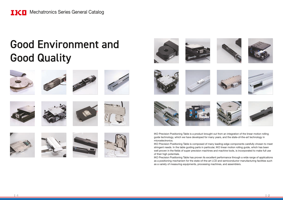
IKO Precision Positioning Table is a product brought out from an integration of the linear motion rolling
guide technology, which we have developed for many years, and the state-of-the-art technology in
microelectronics.
IKO Precision Positioning Table is composed of many leading-edge components carefully chosen to meet
stringent needs. In the table guiding parts in particular, IKO linear motion rolling guide, which has been
well proven in the fields of super precision machines and machine tools, is incorporated to make full use
of their high potentials.
IKO Precision Positioning Table has proven its excellent performance through a wide range of applications
as a positioning mechanism for the state-of-the-art LCD and semiconductor manufacturing facilities such
as a variety of measuring equipments, processing machines, and assemblers.
Ⅰ̶1 Ⅰ̶2
Page3
IKO Types and Characteristics of Mechatronics Series
2012.05.15 Ready for the press CAT-1556 Front facing Ⅰ01-03
MECHATRONICS SERIES Classification and features
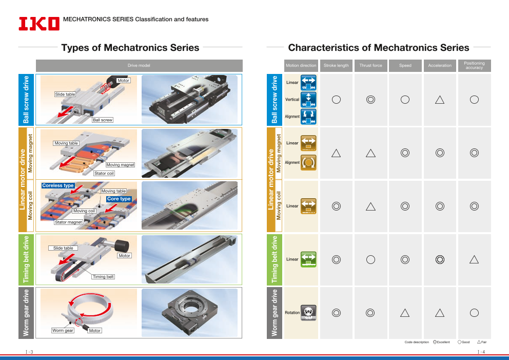
Types of Mechatronics Series Characteristics of Mechatronics Series
Drive model Motion direction Stroke length Thrust force Speed Acceleration Positioning
accuracy
Motor Linear
Slide table
Vertical
Alignment
Ball screw
Moving table Linear
Moving magnet Alignment
Stator coil
Coreless type
Moving table
Core type
Linear
Moving coil
Stator magnet
Slide table
Motor
Linear
Timing belt
Rotation
Worm gear Motor
Code description Excellent Good Fair
Ⅰ̶3 Ⅰ̶4
Worm gear drive Timing belt drive Linear motor drive Ball screw drive
Moving coil Moving magnet
Worm gear drive Timing belt drive Linear motor drive Ball screw drive
Moving coil Moving magnet
Page4
IKO Mechatronics Series INDEX
2012.05.15 Ready for the press CAT-1556 Ⅰ04-26
MECHATRONICS SERIES INDEX
Precision Positioning Table TE Precision Positioning Table TU Precision Positioning Table LB Nano Linear NT
● High-strength aluminum alloy is used for main components ● High rigidity U-shaped track rail adopted ● High-speed type using a timing belt drive ● Pursuing ultimate compactification
● Light weight, low profile and compact positioning table ● Various table specifications are available according to your use. ● Parallel arrangement of Linear Way ensures stable and high operating performance. ● Very low profile of NT38V: only 11mm
● A wide variety of selections support optimal choice according to your use.
Ball screw drive Ball screw drive Timing belt drive
Linear Linear Linear Linear motor drive
Linear
NT…V NT…XZ
TE…B Ⅱ-4 TU Ⅱ-32 TSLB Ⅱ-232 NT…H NT…XZH Ⅱ-244
Precision Positioning Table L Precision Positioning Table LH Alignment Stage SA Linear Motor Table LT
● Standard type highly-proven in various fields ● Component parts from rigorous selection ensure high accuracy and reliability. ● Sectional height of 3 axes X, Y and θ is only 52mm (SA65DE). ● Both high speed and high resolution are achieved.
● Parallel arrangement of Linear Ways with stable performance ● High rigidity and large carrying mass ● X- and Y-axis: 0.1μm, θ-axis: excellent resolution as high as 0.25 sec (SA200DE) ● High acceleration / deceleration, high response and smooth operations
● Long term maintenance free specification with C-Lube built in
Ball screw drive Ball screw drive Linear motor drive
Linear Linear Alignment Linear motor drive
Linear Linear
TSLH…M LT…CE LT…H
TSL…M Ⅱ-102 CTLH…M Ⅱ-122 SA…DE Ⅱ-276 LT…LD Ⅱ-294
Super Precision Positioning Table TX Cleanroom Precision Positioning Table TC Alignment Table AT Rotation Stage SK
● Achieved ultimate positioning performance with rolling guide type ● Optional for use in high cleanliness environment for ● High accuracy positioning ensuring precise angle correction ● Crossed Roller Bearings ensure high rigidity and compactness
● High accuracy attained by fully-closed loop control semiconductor and LCD manufacturing machines ● Crossed Roller Bearing ensures high rigidity and compactness. ● Allows smooth, high-accuracy positioning
● Light weight, low profile and compact positioning table ● Direct mounting of the table or test object reduces labor
hours required for design work
Ball screw drive Ball screw drive
Linear Ball screw drive Alignment
Linear Worm gear drive
TX…M Rotation
CTX…M Ⅱ-150 TC…EB Ⅱ-172 AT Ⅱ-322 SK…W Ⅱ-334
Micro Precision Positioning Table TM Precision Positioning Table TS/CT Alignment Module AM Precision Elevating Table TZ
● Ground ball screw drive realizes ultra-small size with ● Compact structure with low profile ● Supports free designing of stage according to your use ● Unique wedge mechanism ensures compact and high
sectional height of 20mm and width of 17mm. ● Crossed Roller Way guaranteeing high reliability and high accuracy ● Control tolerance of height within ±10μm accuracy vertical positioning.
● High positioning accuracy and excellent durability ● TZ…X achieving high accuracy and high rigidity through
TS CT
adoption of C-Lube Linear Roller Way Super X
Ball screw drive Ball screw drive
Ball screw drive Linear Alignment
Linear Ball screw drive
Vertical
TM Ⅱ-190 Ⅱ-208 AM Ⅱ-342 TZ…H TZ…X Ⅱ-356
Ⅰ̶5 Ⅰ̶6
Page5
Models and Size Variations
2012.05.15 Ready for the press CAT-1556 Ⅰ04-26
Models and Size Variations ①
A Variety of Models and Variations
Precision Positioning Table TE Precision Positioning Table L
Ball screw drive Ball screw drive
TE···B Linear TSL···M Linear
● High-strength aluminum alloy is used for main components ● Standard type highly-proven in various fields
● Light weight, low profile and compact positioning table ● Parallel arrangement of Linear Ways with stable performance
● High accuracy positioning ● High running accuracy and positioning accuracy
● Long term maintenance free specification with C-Lube built in ● Many size variations support easy multi-axis system configurations.
● Excellent cost performance ● Long term maintenance free specification with C-Lube built in
Specification Accuracy Specification Accuracy
Maximum stroke Maximum speed Ball screw lead Positioning repeatability Maximum stroke
Model and size Model and size Maximum speed Ball screw lead Positioning repeatability
(mm) (mm/s) (mm) Positioning accuracy (mm) (mm/s) (mm) Positioning accuracy
TE50B 410 800 4, 8 Lost motion TSL 90 M 300 500 5, 10 Lost motion
TE60B 600 1 000 5, 10, 20 Parallelism in table motion A TSL 120 M 600 500 5, 10 Parallelism in table motion A
TE86B 800 1 860 10, 20 Parallelism in table motion B TSL 170 M 500 500 5, 10 Parallelism in table motion B
Attitude accuracy TSL 170 S M 1 000 500 5, 10 Attitude accuracy
Straightness See page TSL 220 M 1 000 500 5, 10 Straightness See page
Backlash Ⅱ–4 Backlash Ⅱ–102
Precision Positioning Table TU Precision Positioning Table LH
Ball screw drive Ball screw drive
TU TSLH··· (Single-axis
Linear M specification)
(Two-axis
● Original high rigidity U-shaped track rail adopted CTLH···M specification) Linear
● Various table specifications are available according to your use.
● Slide table with high accuracy and high rigidity in a single structure ● Component parts from rigorous selection ensure high accuracy and reliability.
● Easy ordering just by specifying the identification ● High rigidity and large carrying mass
number for the required functions and performance ● High running accuracy and positioning accuracy
Specification Accuracy ● The series including ultra large size with table width of 420mm
●
Maximum stroke Long term maintenance free specification with C-Lube built in
Model and size Maximum speed Ball screw lead Positioning repeatability
(mm) (mm/s) (mm) Positioning accuracy Specification Accuracy
TU 25 100 400 4 Lost motion Maximum stroke Maximum speed Ball screw lead Positioning repeatability
Model and size
TU 30 230 500 5 Parallelism in table motion A (mm) (mm/s) (mm) Positioning accuracy
TU 40 285 800 4, 8 Parallelism in table motion B TSLH120M 300 500 5, 10 Lost motion
TU 50 560 1 000 5, 10 Attitude accuracy TSLH220M 400 500 5, 10 Parallelism in table motion A
TU 60 1 010 1 860 5, 10, 20 Straightness TSLH320M 500 448 5, 10 Parallelism in table motion B
TU 86 1 400 1 480 10, 20 Backlash TSLH420M 800 448 5, 10 Attitude accuracy
TU 100 1 140 1 110 20 CTLH120M 300 × 300 500 5, 10 Straightness
See page See page
TU 130 1 260 1 110 25 CTLH220M 400 × 400 500 5, 10 Backlash
Ⅱ–32 Ⅱ–122
CTLH320M 500 × 500 448 5, 10
1N=0.102kgf=0.2248lbs.
Ⅰ̶7 1mm=0.03937inch Ⅰ̶8
Page6
2012.05.15 Ready for the press CAT-1556 Ⅰ04-26
Models and Size Variations ②
A Variety of Models and Variations
Super Precision Positioning Table TX Micro Precision Positioning Table TM
Ball screw drive Ball screw drive
TX···M (Single-axis
specification) TM Linear
CTX···M (Two-axis
specification) Linear ● Ground ball screw drive realizes ultra-small size with
sectional height of 20mm and width of 17mm.
● Achieved ultimate positioning performance with rolling guide type ● High positioning accuracy and excellent durability
● Fully-closed loop control equipped with super high ● Two types of slide table shapes selectable according to needs
accuracy linear encoder ensuring high accuracy ● Super-miniature sensor can be built in.
● Control method selectable according to needs Accuracy
● Long term maintenance free specification with C-Lube built in Specification Positioning repeatability
Maximum stroke Maximum speed Ball screw lead Positioning accuracy
Specification Accuracy Model and size
(mm) (mm/s) (mm) Lost motion
Maximum stroke Maximum speed Ball screw lead Positioning repeatability
Model and size TM15 60 75 0.5, 1.0, 1.5 Parallelism in table motion A
(mm) (mm/s) (mm) Positioning accuracy TM15G 50 75 0.5, 1.0, 1.5 Parallelism in table motion B
TX 120M 300 500 5, 10 Lost motion Attitude accuracy
TX 220M 400 500 5, 10 Parallelism in table motion A See page
Straightness
TX 320M 500 448 5, 10 Parallelism in table motion B Ⅱ–190
Backlash
TX 420M 800 448 5, 10 Attitude accuracy
See page
CTX 120M 300 × 200 500 5, 10 Straightness
Ⅱ–150
CTX 220M 400 × 300 500 5, 10 Backlash Precision Positioning Table TS/CT
Ball screw drive
Cleanroom Precision Positioning Table TC TS (Single-axis specification)
Ball screw drive
TC···EB CT (Two-axis specification)
Linear
Linear
● Compact structure with low profile
● Optional for use in high cleanliness environment for ● Crossed Roller Way guaranteeing high reliability and
semiconductor and LCD manufacturing machines high accuracy positioning
● Light weight, low profile and compact positioning table ● Compact design achieved by utilizing wide area of slide table
● Compatible with cleanliness class 3 Specification Accuracy
● Long term maintenance free specification with C-Lube built in Maximum stroke(mm) Maximum speed Ball screw lead Positioning repeatability
Model and size
X-axis Y-axis (mm/s) (mm) Positioning accuracy
Specification Accuracy TS 55/ 55 ± 7.5 30 1 Lost motion
TS 75/ 75 ± 12.5 30 1
Maximum stroke Maximum speed Ball screw lead Positioning repeatability ±
Model and size TS 125/ 125 25 250 1, 2, 5 Parallelism in table motion A
(mm) (mm/s) (mm) Positioning accuracy TS 125/ 220 ± 60 250 2, 5 Parallelism in table motion B
TS 220/ 220 ± 60 250 2, 5
TC50EB 200 400 4, 8 Lost motion TS 220/ 310 ± 90 250 2, 5 Attitude accuracy
TC60EB 500 500 5, 10 Parallelism in table motion A TS 260/ 350 ± 125 250 2, 5 Straightness
±
TC86EB 800 1 000 10, 20 Parallelism in table motion B CT 55/ 55 7.5 ± 7.5 30 1 Backlash
CT 75/ 75 ± 12.5 ± 12.5 30 1
Attitude accuracy CT 125/ 125 ± 25 ± 25 250 1, 2, 5
See page
Straightness CT 220/ 220 ± 60 ± 60 250 2, 5 See page
Ⅱ–172 CT 260/ 350 ± 75 ± 125 250 2, 5 Ⅱ–208
Backlash CT 350/ 350 ± 125 ± 125 250 2, 5
1N=0.102kgf=0.2248lbs.
Ⅰ̶9 1mm=0.03937inch Ⅰ̶10
Page7
2012.05.15 Ready for the press CAT-1556 Ⅰ04-26
Models and Size Variations ③
A Variety of Models and Variations
Precision Positioning Table LB Nano Linear NT
Timing belt drive Standard Type Linear motor drive
TSLB Linear NT···V Linear
● Timing belt drive achieves high speed travel at ● Pursuing ultimate compactification
1,500mm/s. ● Very low profile of NT38V: only 11mm
● Parallel arrangement of Linear Way ensures stable ● A wide variety of selections support optimal choice according to your use.
and high operating performance. ● High acceleration / deceleration ensuring highly responsive positioning
● Long stroke up to 1,200mm ● Two-axis combination of X and Y
Specification Accuracy
High Accuracy Type
Maximum stroke Maximum speed Resolution Positioning repeatability Linear motor drive
Model and size
(mm) (mm/s) (mm) Positioning accuracy
TSLB 90 600 1 500 0.1 Lost motion NT···H Linear
TSLB 120 1 000 1 500 0.1 Parallelism in table motion A
TSLB 170 1 200 1 500 0.1 Parallelism in table motion B ● Pursuing ultimate compactification
Attitude accuracy
● High attitude accuracy
Straightness
● High speed stability
Backlash See page ● Simple system configuration
Ⅱ–232
Pick and Place Unit
NT···XZ Linear motor drive
NT···XZH Linear
● Pursuing ultimate compactification
● High-tact positioning
● Ultrathin and space saving
● Operation monitoring function
Specification Accuracy
Maximum stroke Maximum speed Resolution Item NT···V NT···H NT···XZ
Model and size
(mm) (mm/s) (μm) Positioning repeatability
NT38V 18 500 0.1, 0.5 Positioning accuracy
NT55V 65 1 300 0.1, 0.5 Lost motion
NT80V 120 1 300 0.1, 0.5 Parallelism in table motion A
NT88H 65 400 0.01, 0.05 Parallelism in table motion B
NT80XZ 45 1 300 0.1, 0.5 Attitude accuracy
NT90XZH 25 1 300 0.1, 0.5 Straightness
Backlash
See page
Ⅱ–244
1N=0.102kgf=0.2248lbs.
Ⅰ̶11 1mm=0.03937inch Ⅰ̶12
Page8
2012.05.15 Ready for the press CAT-1556 Ⅰ04-26
Models and Size Variations ④
A Variety of Models and Variations
Alignment Stage SA Linear Motor Table LT
Linear motor drive Compact Type Linear motor drive
SA···DE Linear
Alignment LT···CE Linear
● Slim and compact design with sectional height of ● Compact
3 axes, X, Y and θ being only 52mm (SA65DE) ● High static stability
● X- and Y-axis: 0.1μm, θ-axis: excellent ● High speed stability
resolution as high as 0.36 sec (SA120DE) ● High acceleration / deceleration and high response
● Free and independent combination of X, Y and θ ● Long term maintenance free specification with C-Lube built in
Specification Accuracy
Long Stroke Type
Maximum stroke Positioning repeatability Linear motor drive
Model and size Maximum speed Resolution
Maximum operating angle Positioning accuracy
SA 65 DE/X 10( mm) 500(mm/s) 0.1, 0.5(μm) Lost motion LT···LD Linear
SA 120 DE/X 20( mm) 800(mm/s) 0.1, 0.5(μm) Parallelism in table motion A
SA 200 DE/X 20( mm) 800(mm/s) 0.1, 0.5(μm) Parallelism in table motion B ● Super long stroke
SA 65 DE/S 50( degree) 720(degree/s) 0.64(s) Attitude accuracy
● High static stability
SA 120 DE/S 60( degree) 400(degree/s) 0.36(s) Straightness
● High speed stability
SA 200 DE/S 280( degree) 270(degree/s) 0.25(s) Backlash See page ● Both high speed and high resolution are achieved.
Ⅱ–276 ● Long term maintenance free specification with C-Lube built in
High Thrust Type Linear motor drive
LT···H Linear
● High thrust
● High acceleration / deceleration, high response and smooth operations
● High static stability
● Air-cooling capable
● Long term maintenance free specification with C-Lube built in
Specification Accuracy
Maximum stroke Maximum speed Resolution Item LT···CE LT···LD LT···H
Model and size
(mm) (mm/s) (μm) Positioning repeatability
LT100CE 1 000 2 000 0.1, 0.5, 1.0 Positioning accuracy
LT150CE 1 200 2 000 0.1, 0.5, 1.0 Lost motion
LT130LD 2 760 3 000 0.1, 0.5, 1.0 Parallelism in table motion A
LT170LD 2 720 3 000 0.1, 0.5, 1.0 Parallelism in table motion B
LT170H 2 670 1 500 0.1, 0.5, 1.0 Attitude accuracy
Straightness
Backlash
See page
Ⅱ–294
1N=0.102kgf=0.2248lbs.
Ⅰ̶13 1mm=0.03937inch Ⅰ̶14
Page9
2012.05.15 Ready for the press CAT-1556 Ⅰ04-26
Models and Size Variations ⑤
A Variety of Models and Variations
Alignment Table AT Alignment Module AM
Ball screw drive Ball screw drive
AT Alignment AM Alignment
● High accuracy positioning ensuring precise ● Supports free designing of stage according to
angle correction your use
● Crossed Roller Bearing ensures high rigidity and ● Control tolerance of height within ±10μm
compactness. ● Variety of positioning operations in combination
● High positioning repeatability of X, Y, and θ
● A series of 3 sizes ● Ideal for large size equipment
Specification Accuracy ● High accuracy, high rigidity, and high reliability
Maximum operating angle Ball screw lead Rotator resolution Positioning repeatability Specification Accuracy
Model and size
(degree) (mm) (μm) Positioning accuracy Maximum stroke Length of track rail Ball screw lead Positioning repeatability
Model and size
AT120 ± 5 1 1 Lost motion (mm) (mm) (mm) Positioning accuracy
AT200 ± 5 1 1 Parallelism in table motion A AM25 30 130 4 Lost motion
AT300 ± 10 2 2 Parallelism in table motion B AM40 30 180 4 Parallelism in table motion A
Attitude accuracy AM60 90 290 5 Parallelism in table motion B
Straightness AM86 120 390 5 Attitude accuracy
See page See page
Backlash Straightness
Ⅱ–322 Backlash Ⅱ–342
Rotation Stage SK Precision Elevating Table TZ
Worm gear drive Ball screw drive
SK…W Rotation TZ Linear
● Crossed Roller Bearings ensure high rigidity and ● Unique wedge mechanism ensures compact and
compactness high accuracy vertical positioning.
● Allows smooth, high-accuracy positioning ● TZ…X achieving high accuracy and high rigidity
● Direct mounting of the table or test object reduces through adoption of C-Lube Linear Roller Way
labor hours required for design work Super MX
● Linear encoder mountable
● Long term maintenance free with C-Lube built in
Specification Accuracy ● A series of two types of reduction ratios
Table diameter Operating angle range Maximum number of Positioning repeatability
Model and size table revolutions
(mm) (degree) Specification Accuracy
(min-1) Positioning accuracy
Maximum stroke Maximum speed Ball screw lead Positioning repeatability
SK120W 115 360 Lost motion
5 Model and size
(mm) (mm/s) (mm) Positioning accuracy
SK120W/SC 120 320 Parallelism in table motion A
TZ120X 10 100 4 Lost motion
Parallelism in table motion B
TZ200H 24 125 5 Parallelism in table motion A
Attitude accuracy
TZ200X 24 125 5 Parallelism in table motion B
Straightness
Attitude accuracy
Backlash See page See page
Straightness
Ⅱ–334 Backlash Ⅱ–356
1N=0.102kgf=0.2248lbs.
Ⅰ̶15 1mm=0.03937inch Ⅰ̶16
Page10
IKO Evolving Positioning Mechanism
2012.05.15 Ready for the press CAT-1556 Ⅰ04-26
Evolving Positioning Mechanism ①
For light weight and low profile innovative tables For ultimate compactification
Precision Positioning Table TE Micro Precision Positioning Table TM
TE···B TM
Ground ball screw specification
realizes ultra-small size with sectional
height of 20mm and width of 17mm.
Micro Linear Way L with track rail width of 2mm is adopted in the
table guiding parts, and miniature ball screw with screw diameter
of 2mm is used in the feeding mechanism. The unparalleled low
cross sectional height in the ground ball screw drive is
achieved.
Motor
Cover
Slide table
Precision ground
ball screws
Angular bearing
High-strength aluminum alloy is used for main components.
Light weight and compact structure with slide table assembled 1 Micro Linear Way L
7m
inside the U-shaped bed! m
Sensor Bed
● Mass unit: kg Nano Linear NT
Bed width(mm) TU TE···B NT···V
50 1.8 0.52
60 3.3 1.0 Pursuing ultimate compactification
86 10.9 3.7 NT38V10, the smallest in the series,
The value shows the mass of the entire table with 1 standard table. is only 11mm in sectional height,
38mm in table width and 62mm in
entire length.
The occupied space is not
increased even when tables are
layered in X and Y, so further
Respective sensors to be attached miniaturization of the positioning
directly into the mounting groove mechanism is promoted.
Slide table and linear motion
Model NT···V
rolling guide integrated in a NT38V10 NT38V18 NT55V25 NT55V65 NT80V25 NT80V65 NT80V120
single structure to ensure low
profile and compact design! Model
and size
Ultra light weight achieved
38
50 50 through the use of slide table Sectional
and bed made of high-strength dimension
26 55 80
TU50 TE50B aluminum alloy!
1N=0.102kgf=0.2248lbs.
Ⅰ̶17 1mm=0.03937inch Ⅰ̶18
50
26
11
14
16
20mm
Page11
2012.05.15 Ready for the press CAT-1556 Ⅰ04-26
Evolving Positioning Mechanism ②
For attaining both
For higher accuracy high accuracy positioning and high speed
Super Precision Positioning Table TX Linear Motor Table LT
TX···M, CTX···M LT···LD
Super high positioning accuracy and resolution guaranteed Direct drive enables both high-precision
with an onboard super high accuracy linear encoder! positioning and high speed.
Adoption of C-Lube Linear Roller Way Super MX ensures ultimate Supports high speed operation required for long stroke motion
running performance. Fully-closed loop control is established by It is possible to perform high-speed motion of up to 3,000mm/s.
super high resolution linear encoder to ensure high positioning
accuracy over the whole stroke length. 6 000
Maximum speed: 3,000mm/s
10.0 5 000
Test portion: CTX220M-4030 Actual speed
X-axis 4 000 Command speed
5.0 Y-axis 3 000
2 000
0.0 1 000
0
-5.0 -1 000
0 0.1 0.2 0.3 0.4 0.5 0.6 0.7 0.8 0.9
Time s
-10.0
100 200 300 400
Stroke mm
Nano Linear NT For
NT···H high speed stability
High attitude accuracy is realized! Linear Motor Table LT
Combination of parts processed with high accuracy and LT···CE, LT···LD, LT···H
Anti-Creep Cage Crossed Roller Way realizes attitude accuracy of
5 sec or less. Variations in attitude due to movement is minimized, Direct drive and advanced servo technology has achieved high
which ensures high positioning repeatability. speed stability.
30
25 Attitude accuracy: 5 sec or less 12
20
11.5 10mm/s speed stability(measured frequency: 1,000Hz): ±1.78%
15
10 Pitching 11
5
0 10.5
0 -5 Yawing 10
-10
- 9.5
15
-20 9
-25 8.5
-30
0 10 20 30 40 50 60 8
0 1 2 3 4 5
Stroke mm
Time s
1N=0.102kgf=0.2248lbs.
Ⅰ̶19 1mm=0.03937inch Ⅰ̶20
Attitude accuracy sec Positioning accuracy μm
Speed mm/s
Speed mm/s
Page12
2012.05.15 Ready for the press CAT-1556 Ⅰ04-26
Evolving Positioning Mechanism ③
For choosing from a wide variety of options For clean environment applications
Easy ordering is possible right now just by specifying the Cleanroom Precision Positioning Table TC
identification number for the required functions and performance! TC···EB
Precision Positioning Table TU Precision Positioning Table TE Cleanliness class 3 is achieved!
TU TE···B Stainless sheet with excellent corrosion resistance and side cover
seal up drive parts and slide table guiding parts. Stainless sheet is
pressed onto the side cover by resin roller within the slide table.
The structure which ensures proper attraction by the strong
magnet sheet prevents dust from generating to the surrounding of
the table by air suction from the sealed internal space.
TC50EB150 Stroke length : 50mm oke length : 200mm
Speed : 200mm/s TC50EB300 Str
Speed : 400mm/s
(Ball screw lead: 4mm) Suction amount : 5L/min (Ball screw lead: 8mm) Suction amount : 10L/min
100 000 100 000
10 000 Upper limit of class 5 10 000 Upper limit of class 5
1 000 Upper limit of class 4
Shape of slide table Motor folding back specification 1 000 Upper limit of class 4
100 Upper limit of class 3 100 Upper limit of class 3
Two types of shape are available according to needs. Shortening the overall length of the table will
contribute to space-saving. 10 Upper limit of class 2 10 Upper limit of class 2
Measurement value
Upper limit of class 1 Upper limit of class 1 Measurement value
1 1
With bridge cover 0.1μm or more 0.2μm or more 0.3μm or more 0.5μm or more 0.1μm or more 0.2μm or more 0.3μm or more 0.5μm or more
Particle diameter Particle diameter
A specification with bridge
cover is available for TC60EB300 Stroke length : 200mm e length : 500mm
Speed : 500mm/s TC60EB600 Strok
Speed : 500mm/s
(Ball screw lead: 10mm) Suction amount : 30L/min (Ball screw lead: 10mm) Suction amount : 30L/min
preventing foreign matter 100 000 100 000
Standard With flange from falling onto
Short, standard, long Short, standard, long the table. 10 000 Upper limit of class 5 10 000 Upper limit of class 5
1 000 Upper limit of class 4 1 000 Upper limit of class 4
Number of slide tables Table with bellows
100 Upper limit of class 3 100 Upper limit of class 3
Two slide tables can be mounted on the track rail A specification with bellows is available Measurement value Measurement value
depending on the applied load and the moment. for preventing foreign matter from 10 Upper limit of class 1 10 Upper limit of class 1
intruding into the inside of Upper limit of class 2 Upper limit of class 2
1 1
the table. 0.1μm or more 0.2μm or more 0.3μm or more 0.5μm or more 0.1μm or more 0.2μm or more 0.3μm or more 0.5μm or more
Particle diameter Particle diameter
TC86EB640 Stroke length : 200mm ke length : 800mm
Speed : 1 000mm/s TC86EB940 Stro
Speed : 560mm/s
(Ball screw lead: 20mm) Suction amount : 70L/min (Ball screw lead: 20mm) Suction amount : 40L/min
100 000 100 000
Black chrome surface treatment
10 000 Upper limit of class 5 10 000 Upper limit of class 5
Type and lead of ball screw Black permeable film is applied on
1 000 Upper limit of class 4 1 000 Upper limit of class 4
Rolled ball screw or ground ball screw can be the surface of slide table and ball
selected according to the required accuracy. screw to improve
100 Upper limit of class 3 100 Upper limit of class 3
Measurement value
Ball screw lead is also selectable. corrosion resistance.
10 Measurement value
Upper limit of class 1 10 Upper limit of class 1
Upper limit of class 2 Upper limit of class 2
1 1
0.1μm or more 0.2μm or more 0.3μm or more 0.5μm or more 0.1μm or more 0.2μm or more 0.3μm or more 0.5μm or more
Particle diameter Particle diameter
1N=0.102kgf=0.2248lbs.
Ⅰ̶21 1mm=0.03937inch Ⅰ̶22
Particle concentration number Particle concentration number Particle concentration number
of particles/m3 of particles/m3 of particles/m3
Particle concentration number Particle concentration number Particle concentration number
of particles/m3 of particles/m3 of particles/m3
Page13
2012.05.15 Ready for the press CAT-1556 Ⅰ04-26
Evolving Positioning Mechanism ④
For maintenance free For a wider variety of needs
Original and world's first structure with【 C-Lube】 Extensive experience in special stages will help us precisely
Gentle to The Earth address your particular needs such as stages related to various
C-Lube integrated axis configurations. If needed, please contact IKO.
Lubrication oil is carried through Lubrication oil is directly supplied to
circulation of rolling elements surfaces of the rolling elements
The lubrication oil is supplied directly to the rolling elements, not to The surface of capillary lubricating element is always covered
the track rail. with the lubrication oil.
When rolling elements make contact with the capillary lubricating Lubrication oil is continuously supplied to the surface of rolling
element integrated with the circulation path of slide unit rolling elements by surface tension in the contact of capillary
elements, the lubrication oil is supplied to surfaces of rolling lubricating element surface and rolling elements.
elements and carried to the loading area through circulation of On the surface of capillary lubricating element with which the
rolling elements. rolling elements make contact, new lubrication oil is always
This results in adequate lubrication oil being properly maintained in supplied from the other sections.
the loading area and lubrication performance will last for a long time.
Cylindrical rollers Cylindrical rollers
C-Lube
Cylindrical rollers
Lubrication
oil film
Surface
tension
Track rail
Slide unit stroke direction
C-Lube Capillary action C-Lube ▲ Liquid crystal substrate manufacturing equipment ▲ Liquid crystal substrate manufacturing equipment
C-Lube Linear Way C-Lube Linear Roller Way
The aquamarine end plate The aquamarine end plate
is the symbol of is the symbol of
maintenance free. maintenance free.
▲ Electronic parts inspection equipment ▲ Liquid crystal substrate inspection equipment
● Precision Positioning Table TE ● Super Precision Positioning Table TX
● Precision Positioning Table L ● Nano Linear NT
● Precision Positioning Table LH ● Alignment Stage SA
● Cleanroom Precision Positioning Table TC ● Linear Motor Table LT
● Precision Elevating Table TZ ▲ Liquid crystal substrate inspection equipment
Series with【 C-Lube】 built in
Ⅰ̶23 Ⅰ̶24
Page14
Table of contents
2012.04.27 Initial draft CAT-1556 Table of contents Ⅱ01-02
Explanation and Dimension Table for Respective Product Series
● Precision Positioning Table TE Explanation・・Ⅱ- 5 Dimension Table・・Ⅱ- 19
● Precision Positioning Table TU Explanation・・Ⅱ- 33 Dimension Table・・Ⅱ- 69
● Precision Positioning Table L Explanation・・Ⅱ-103 Dimension Table・・Ⅱ-116
● Precision Positioning Table LH Explanation・・Ⅱ-123 Dimension Table・・Ⅱ-137
● Super Precision Positioning Table TX Explanation・・Ⅱ-151 Dimension Table・・Ⅱ-164
● Cleanroom Precision Positioning Table TC
Explanation・・Ⅱ-173 Dimension Table・・Ⅱ-186
● Micro Precision Positioning Table TM
Explanation・・Ⅱ-191 Dimension Table・・Ⅱ-205
● Precision Positioning Table TS/CT
Explanation・・Ⅱ-209 Dimension Table・・Ⅱ-222
● Precision Positioning Table LB Explanation・・Ⅱ-233 Dimension Table・・Ⅱ-240
● Nano Linear NT Explanation・・Ⅱ-245 Dimension Table・・Ⅱ-270
● Alignment Stage SA Explanation・・Ⅱ-277 Dimension Table・・Ⅱ-286
● Linear Motor Table LT Explanation・・Ⅱ-295 Dimension Table・・Ⅱ-311
● Alignment Table AT Explanation・・Ⅱ-323 Dimension Table・・Ⅱ-330
● Rotation Stage SK Explanation・・Ⅱ-335 Dimension Table・・Ⅱ-340
● Alignment Module AM Explanation・・Ⅱ-343 Dimension Table・・Ⅱ-351
● Precision Elevating Table TZ Explanation・・Ⅱ-357 Dimension Table・・Ⅱ-365
● Driver Specification for Linear Motor Drive Tables
Explanation・・Ⅱ-370
U.S. PATENTED
Precision Positioning Table TE Alignment Stage SA General Explanation
No. 8353225 No. 7202584
Precision Positioning Table TU 7091636
7030518
No. 6880975 6240796 ● General Explanation・・・・・・・・・・・・・・・・・・・・・・・・・・・・・・ Ⅲ-2
6851857 6176617 Linear Motor Table LT
6634246 6082899 No. 6734583
6517244 5967667 6348748
6461045 5435649
6309107 Alignment Table AT
No. 6722289
Micro Precision Positioning Table TM
No. 8413531 Precision Elevating Table TZ
8061227 No. 7234675
Nano Linear NT
No. 7633188
7514824
Ⅱ̶1 Ⅱ̶2
Page15
Precision Positioning Table TE|TE…B
TE…B
Ⅱ̶3 Ⅱ̶4
TE…B
Page16
Precision Positioning Table TE
Ball screw
TE・・・B Linear Points ● Table specification is selectable
according to your use
2 There are two types in the shape of slide table: standard and
● Light weight, low profile and high- with flange. The number of slide tables, motor folding back
precision positioning table specification, ball screw lead, with or without a dust protection
cover, installation of various sensors can be selected, you can
1 Light weight, low profile and compact positioning table using
Motor bracket select an optimal product for the specifications of your machine
high-strength aluminum alloy for its main components with a and device.
Slide table slide table assembled inside a U-shaped bed.
The mass of the entire table is reduced to about 40% of TU ● Excellent cost performance
series. Low cross sectional height (26mm for TE50B, 33mm
for TE60B, and 46mm for TE86B). Moreover, the structure of
3 The excellent cost performance is realized by reducing the
various sensors directly installable on sensor mounting groove number of parts, and optimizing the part shapes.
of the bed contributes to the miniaturization.
Ball screw
Comparison with Precision Positioning Table TU
● Sectional height
TE50B TU50 TE60B TU60 TE86B TU86
Sensor mounting
groove
Bed
Linear Way
● Mass
End bracket Model and size Stroke length(mm) Overall length(mm) Mass(kg) Mass / 100mm(kg)
TE50B 60 218 0.52 0.24
TU50 60 226 1.8 0.80
TE60B 100 269 1.0 0.37
TU60 100 298 3.3 1.11
TE86B 300 523 3.7 0.71
Major product specifications Accuracy TU86 250 498 10.9 2.19
unit: mm
Driving method Precision ball screw Positioning repeatability ±0.002~0.020
Linear motion rolling guide Linear Way(ball type) Positioning accuracy 0.035~0.065 Variation
Built-in lubrication part Lubrication part "C-Lube" is built-in Lost motion −
Bed width(mm)
Material of table and bed High-strength aluminum alloy Parallelism in table motion A − Shape Model
50 60 86
Sensor Select by identification number Parallelism in table motion B 0.008~0.016
Standard TE…BS ☆ ☆ ☆
Attitude accuracy −
Straightness −
With flange TE…BF ☆ ☆ ☆
Backlash 0.005
1N=0.102kgf=0.2248lbs.
Ⅱ̶5 1mm=0.03937inch Ⅱ̶6
TE…B
Page17
Identification Number Identification Number and Specification
Table 2.1 Application of motor attachment (motor inline specification)
Example of an Identification Number 1 2 1 3 4 5 6 7 8 9
Motor to be used Flange Motor attachment
Rated output size
TE 50 B F 300 / AT001 8 S C 3 Type Manufacturer Series Model TE50B TE60B TE86B
W mm
SGM7J-A5A AT001 AT002 -
50
SGM7A-A5A AT001 AT002 -
YASKAWA □40
SGM7J-01A - AT002 -
1 Model ELECTRIC Σ-7 100
Page Ⅱ-7 CORPORATION SGM7A-01A - AT002 -
SGM7J-02A - - AT003
200 □60
2 Size SGM7A-02A - - AT003
Page Ⅱ-7
HG-MR053 AT001 AT002 -
50
HG-KR053/HK-KT053W AT001 AT002 -
3 Shape of slide table Mitsubishi □40
Page Ⅱ-7 AC servo HG-MR13 - AT002 -
Electric J4/J5 100
motor
Corporation HG-KR13/HK-KT13W - AT002 -
4 Bed length HG-MR23 - - AT003
Page Ⅱ-7 200 □60
HG-KR23/HK-KT23W - - AT003
MSMF5A 50 AT004 AT005 -
5 Designation of motor attachment Panasonic □38
Page Ⅱ-7 MINAS A6 MSMF01 100 - AT005 -
Corporation
MSMF02 200 □60 - - AT006
6 Ball screw lead Hitachi Industrial ADMA-R5L 50 AT001 AT002 -
Page Ⅱ-9 □40
Equipment AD ADMA-01L 100 - AT002 -
Systems Co., Ltd ADMA-02L 200 □60 - - AT003
7 Number of slide tables Page Ⅱ-9 ARM46 □42 AT007 - -
ORIENTAL α step ARM66 □60 - - AT008
Stepper
8 Cover specification MOTOR ARM69 □60 - - AT008
Page Ⅱ-9 motor
Co., Ltd. CRK54 □42 AT009 - -
CRK
CRK56( 1) □60 - AT010 AT011
9 Sensor specification Page Ⅱ-9 Note( 1)Applicable to the outer diameter φ8 of motor output shaft.
Remark: For detailed motor specifications, please see respective motor manufacturer's catalog.
Table 2.2 Application of NEMA motor attachment (motor inline specification)
Identification Number and Specification Motor to be used Motor attachment
Flange
Rated
size
Type Manufacturer Series Model output TE50B TE60B TE86B
inch
1 Model W
TE…B: Precision Positioning Table TE
TLY-A110(AA type) 41 □40 AT001 AT002 -
TLY-A120(AA type) 86 □40 AT001 AT002 -
2 Size Size indicates bed width. TLY(metric) TLY-A130(AA type) 140 □40 AT001 AT002 -
Select a size from the list of Table 1. TLY-A220(AA type) 350 □60 - - AT003( 3)
TLY-A230(AA type) 440 □60 - - AT003( 3)
3 Shape of slide table S: Standard table E9043-
TLY-A120( TA
AN type) 86 □42 - -
F: Flange type standard table ATE137( 1)
AC servo TAE9043-
Allen-Bradley TLY-A130(AN type) 140 □42 - -
motor ATE137( 1)
4 Bed length Select a bed length from the list of Table 1. TAE9017-
TLY-A220(AN type) 350 □56.4 - -
ATE135( 1)
TLY(NEMA)
Table 1 Sizes and bed lengths unit: mm 9017-
TLY-A230(AN type) 440 □56.4 - - TAE
Model and size Bed width Bed length ATE135( 1)
TE50B 50 150, 200, 250, 300, 400, 500 TLY-A2530(AN type) -
690 □86 - - TAE9056
ATE134( 1)
TE60B 60 150, 200, 300, 400, 500, 600, 700
TLY-A2540(AN type) 860 □ 9056-
86 - - TAE
TE86B 86 340, 440, 540, 640, 740, 840, 940 ATE134( 1)
Remark: F or stroke length, please see the dimension tables shown in pages of Ⅱ̶19 or later. TAE9043-
NEMA17C - -
ATE110( 1)(2)
TAE9017-
5 AT000 : Motor inline specification Without motor attachment TAE9017-
Designation of motor attachment Servo or ATE096( 1)(2 -
)
AT001 to AT011 : Motor inline specification With motor attachment NEMA23D ATE096( 1)
Stepper
AR000 : Motor folding back specification Without motor attachment (2) TAE9017- -
ATE097( 1)(2)
AR001 to AR008 : Motor folding back specification With motor attachment E9056-
To specify the motor attachment, select it from the list of Table 2.1 and Table 2.2. NEMA34D - - TA
ATE095( 1)(2)
・Please specify motor folding back specification and motor attachment applicable to motor for use. Note( 1) The TAE part numbers are the part number of motor attachment component sold separately. In the TE part number, please choose
・If motor inline specification with motor attachment is specified, the main body is shipped motor attachment code AT000. No Coupling is included. It is required to consider customer’s operation patterns for these motor
with a coupling indicated in the Table 3 mounted. However, the final position adjustment attachment.
should be made by customer since it is only temporarily fixed. For a product without motor (2) Please confirm the length and the diameter of the motor shaft etc., and check the usability of the motor attachment with your motor
beforehand.
attachment (AT000), no coupling is attached.
(3) It is required to change the delivered coupling to XGS-30C-8×12 which is for the 12mm motor shaft by customer.
・If motor folding back specification with motor attachment is specified, "housing applicable to the Remark: For detailed motor specifications, please see respective motor manufacturer’s catalog.
specified motor, pulley (on motor side and ball screw side), cover, motor bracket, belt and bolts
necessary for assembly" are supplied. Motor mounting bolts should be prepared by customer.
1N=0.102kgf=0.2248lbs.
Ⅱ̶7 1mm=0.03937inch Ⅱ̶8
TE…B
Page18
Identification Number and Specification Specifications
Table 2.3 Application of motor attachment (motor folding back specification) Table 4 Accuracy unit: mm
Motor to be used Flange Motor attachment Model Positioning Parallelism in
Bed length Positioning accuracy( 1) Backlash( 1)
Rated output size and size repeatability table motion B
Type Manufacturer Series Model TE50B TE60B TE86B
W mm 150
0.035
SGM7J-A5A AR001 AR002 - 200
50 ±0.002 0.008
SGM7A-A5A AR001 AR002 - 250
TE50B 0.040 0.005
YASKAWA □40 300 (±0.020)
SGM7J-01A - AR002 -
ELECTRIC Σ-7 100 400 0.010
SGM7A-01A - AR002 - 0.045
CORPORATION 500 0.012
SGM7J-02A - - AR003 150
200 □60 0.035
SGM7A-02A - - AR003 200
0.008
HG-MR053 AR001 AR002 - 300 ±0.002 0.040
50
HG-KR053/HK-KT053W AR001 AR002 - TE60B 400 0.005
0.045
500 (±0.020)□40
AC servo Mitsubishi Electric HG-MR13 - AR002 - 0.010
J4/J5 100 600 0.050
motor Corporation HG-KR13/HK-KT13W - AR002 - 700 0.060 0.012
HG-MR23 - - AR003 340 0.040 0.008
200 □60
HG-KR23/HK-KT23W - - AR003 440 0.045
0.010
MSMF5A 50 AR004 AR005 - 540 ±
Panasonic □ 0.002
38 0.050
MINAS A6 MSMF01 100 - AR005 - TE86B 640 0.005
(±0.020) 0.012
Corporation 740 0.055
MSMF02 200 □60 - - AR006 840 0.014
Hitachi Industrial ADMA-R5L 50 AR001 AR002 - 0.065
□40 940 0.016
Equipment Systems AD ADMA-01L 100 - AR002 - Note( 1)This does not apply to table of motor folding back specification.
Co., Ltd ADMA-02L 200 □60 - - AR003 Remark: The values in( ) are reference values provided that the timing belt tension is properly adjusted in motor folding back specification table.
Stepper ORIENTAL MOTOR α step ARM46 □42 AR007 - - Table 5 Maximum carrying mass
motor Co., Ltd. CRK CRK54 □42 AR008 - -
Carrying mass center of Maximum carrying mass
Remark: For detailed motor specifications, please see respective motor manufacturer's catalog.
gravity kg
mm Horizontal direction Vertical direction
Table 3 Coupling models (motor inline specification) Ball screw lead
Model and size
mm Length
Motor Coupling inertia J L
Coupling models Manufacturer C 0 100 200 300 0 100 200 300
attachment ×10-5kg・m2 Height
H
AT001 XGS-19C- 5× 8 Nabeya Bi-tech Kaisha 0.062
0 12 12 7 5 11 7 3.8 2.6
AT002 XGS-19C- 5× 8 Nabeya Bi-tech Kaisha 0.062
100 12 12 7 4.9 6 4.4 2.9 2.1
AT003 XGS-30C- 8×14 Nabeya Bi-tech Kaisha 0.55 4
200 12 11 6 4.7 3.6 2.8 2.3 1.8
AT004 XGS-19C- 5× 8 Nabeya Bi-tech Kaisha 0.062 300 12 10 6 4.6 2.5 2.1 1.8 1.6
AT005 XGS-19C- 5× 8 Nabeya Bi-tech Kaisha 0.062 TE50B
0 12 10 5 3.9 7 5 2.9 2.0
AT006 XGS-30C- 8×11 Nabeya Bi-tech Kaisha 0.55 100 12 8 5 3.6 5 3.4 2.3 1.7
AT007 XGS-19C- 5× 6 Nabeya Bi-tech Kaisha 0.062 8
200 12 7 4.6 3.3 2.8 2.2 1.8 1.4
AT008 XGS-30C- 8×10 Nabeya Bi-tech Kaisha 0.55 300 11 6 4.1 3.1 1.9 1.6 1.4 1.2
AT009 XGS-19C- 5× 5 Nabeya Bi-tech Kaisha 0.062 0 17 17 11 8 13 10 5 3.8
AT010 XGS-19C- 5× 8 Nabeya Bi-tech Kaisha 0.062 100 17 17 11 7 9 6 4.4 3.2
5
AT011 XGS-30C- 8× 8 Nabeya Bi-tech Kaisha 0.55 200 17 16 10 7 5 4.2 3.5 2.8
TAE9043-ATE137 XGS-19C- 5× 6.35 Nabeya Bi-tech Kaisha 0.062 300 17 14 9 7 3.7 3.1 2.7 2.4
TAE9017-ATE135 XGS-30C- 8×12.7 Nabeya Bi-tech Kaisha 0.55 0 17 15 8 5 8 8 4.3 3.0
100 17 11 7 5 7 5 3.4 2.5
TAE9056-ATE134 XGS-34C- 8×15.875 Nabeya Bi-tech Kaisha 1.0 TE60B 10
200 17 9 6 4.8 4.1 3.3 2.7 2.1
Remark: For detailed coupling specification, please see the manufacturer's catalog. 300 13 8 5 4.4 2.8 2.4 2.1 1.8
0 17 9 5 3.8 7 5 3.2 2.2
100 13 6 4.3 3.2 5 3.7 2.5 1.8
6 Ball screw lead 20
Select from among ball screw leads applicable to the sizes and bed lengths shown in the table below. 200 7 4.9 3.5 2.7 3.0 2.4 1.9 1.5
300 5 3.9 3.0 2.4 2.1 1.7 1.5 1.3
Model Ball screw lead mm
Bed length mm 0 36 36 25 18 18 18 13 9
and size 4 5 8 10 20 100 36 35 22 16 18 15 10 7
10
200 36 29 20 15 12 10 8 6
300 or less ○ - ○ - -
TE50B 300 36 24 17 13 9 7 6 5
400 or more - - ○ - - TE86B
0 29 28 16 11 10 10 10 6
600 or less - ○ - ○ -
TE60B 100 29 19 13 10 10 10 7 5
700 - - - - ○ 20
200 23 15 11 8 9 7 6 5
TE86B All - - - ○ ○ 300 17 12 9 7 6 5 4.8 4.3
Remarks 1. The value is for one flange type standard table.
2. The maximum carrying mass is adjusted by the mass when the rating life of the linear motion rolling guide, ball screws, or bearings is 18,000 hours during continuous
7 Number of slide table S: One unit operation at a number of revolutions of the motor of 3000min-1 and an acceleration/deceleration time of 0.2s. The mass calculated is based upon the basic static load
rating of the linear motion rolling guide.
C: Two units 3. Please also check the maximum load mass on page III-18.
8 Cover specification L
0: Without cover
C: With bridge cover (applied to TE…BF)
9 Specification of sensor 0: Without sensor
2: Two units of sensor mounted (limit)
3: Three units of sensor mounted (limit, pre-origin)
4: Four units of sensor mounted (limit, pre-origin, origin) L H
5: Two sensors attached (limit)
6: Three sensors attached (limit, pre-origin) Carrying mass W
7: Four sensors attached (limit, pre-origin and origin sensors)
If sensor mounting (symbol 2, 3, or 4) is specified, the sensor is mounted into the mounting groove on
Carrying mass W
the side of bed, and two detecting plates are attached onto the slide table.
If sensor attachment (symbol 5, 6, or 7) is specified, specified number of sensors are attached including Carrying mass center of gravity Carrying mass center of gravity
mounting screws for sensors, nuts, two detecting plates, and mounting screws for the detecting plates. (horizontal direction) (vertical direction)
1N=0.102kgf=0.2248lbs.
Ⅱ̶9 1mm=0.03937inch Ⅱ̶10
H
TE…B
Page19
Specifications
■ Allowable moment Table 9.1 Specifications of ball screw 1
Model Lead Shaft dia. Basic dynamic load rating C Basic static load rating C0
Allowable moment refers to the maximum static moment that can be used without affecting functions or performance. and size mm mm N N
Therefore, do not exceed the allowable moment value during operation. 4 2 290 3 575
TE50B 8
Table 6 Allowable moment 8 1 450 2 155
5 2 730 4 410
Allowable moment( 1) N・m
Model and size TE60B 10 10 1 720 2 745
T0 TX TY 20 1 636 2 790
TE50B 9.8( 19.6) 9.8( 48.4) 9.8( 48.4) 10 3 820 6 480
TE60B 16.7( 33.4) 16.7( 88.1) 16.7( 88.1) TE86B 12
20 2 300 3 920
TE86B 49.0( 98.0) 49.0( 247.0) 49.0(247.0)
Note( 1) The value in ( ) represents two slide tables in close contact.
Table 9.2 Specifications of ball screw 2 unit: mm
T T T
X Y
0 Model and size Bed length Shaft dia. Overall length
150 192.5
200 242.5
250 292.5
TE50B 8
300 342.5
400 442.5
500 542.5
150 194
200 244
Table 7 Load rating of linear motion rolling guide 300 344
Model Basic dynamic load rating C Basic static load rating C Static moment rating( 1) N・m TE60B 400 10 444
0
and size N N T 500 544
0 TX TY
TE50B 8 490 12 500 211( 422) 99.5( 508) 99.5( 508) 600 644
TE60B 12 400 17 100 354( 708) 151 ( 795) 151 ( 795) 700 744
TE86B 26 800 35 900 1 110( 2 220) 472 (2 400) 472 (2 400) 340 395
Note( 1) In directions indicated in the above figures, the value in ( ) is for two slide tables in close contact. 440 495
540 595
Table 8 Maximum speed TE86B 640 12 695
Maximum speed mm/s 740 795
Bed length
Motor type Model and size
mm Lead Lead Lead Lead Lead 840 895
4mm 5mm 8mm 10mm 20mm 940 995
300 or less 400 - 800 - -
TE50B 400 - - 800 - - Table 10 Moment of inertia of sectional area of bed
500 - - 620 - -
500 or less - 500 - 1 000 -
AC TE60B 600 - 350 - 710 - Y-axis
700 - - - - 960
servomotor 540 or less - - - 930 1 860
640 - - - 830 1 630
TE86B 740 - - - 590 1 170
840 - - - 440 880
940 - - - 340 690
300 or less 120 - 240 - -
TE50B 400 - - 240 - - X-axis
Stepper 500 - - 240 - -
motor 600 or less - 150 - 300 -
TE60B
700 - - - - 600
TE86B 940 or less - - - 300 600
Remark: To measure the practical maximum speed, it is required to consider operation patterns based on the motor to be used and load Moment of inertia of sectional area mm4
Model Center of gravity
conditions. e
and size IX IY mm
TE50B 1.3×10⁴ 1.2×10⁵ 6.4
TE60B 4.7×10⁴ 3.2×10⁵ 8.8
TE86B 2.0×10⁵ 1.3×10⁶ 13.0
1N=0.102kgf=0.2248lbs.
Ⅱ̶11 1mm=0.03937inch Ⅱ̶12
e
TE…B
Page20
Specifications Motor Folding Back Specification
Table 11 Table inertia and starting torque Motor folding back specification is available for Precision Positioning Table TE, space can be saved by folding back the
Table inertia J 2
T( ) motor and reducing the overall length of the table. For dimensions of motor folding back specification, please refer to
×10-5kg・m2
Starting
Bed respective dimension table.
Model Flange type
length Standard table torque
and size standard table For motor folding back specification, assembly should be made by customer since "housing applicable to the specified
T(1
S )mm
Lead Lead N・m motor, pulley (on motor side and ball screw side), cover, motor bracket, belt and bolts necessary for assembly" are supplied.
4mm 5mm 8mm 10mm 20mm 4mm 5mm 8mm 10mm 20mm However, motor mounting bolts should be prepared by customer. The motor attachment can be attached in 4 directions as
150 0.057 - 0.071 - - 0.060 - 0.084 - - indicated in the following figure.
200 0.069 - 0.083 - - 0.072 - 0.096 - - There is difference in dimension between where the motor attachment or the motor is lower than the bottom of the bed
250 0.085 - 0.099 - - 0.088 - 0.112 - -
TE50B 0.03 depending on the motor folding back direction. Do the design ensuring that the peripheral components do not interfere and
300 0.097 - 0.111 - - 0.100 - 0.124 - -
that enough allowance is provided according to the approximate values in the dimension table shown in Page Ⅱ̶25 to Ⅱ̶30.
400 - - 0.139 - - - - 0.152 - -
500 - - 0.167 - - - - 0.180 - -
150 - 0.13 - 0.17 - - 0.14 - 0.20 -
200 - 0.19 - 0.23 - - 0.20 - 0.26 -
300 - 0.26 - 0.30 - - 0.27 - 0.33 -
Motor folding back upward Motor folding back to left
TE60B 400 - 0.33 - 0.36 - - 0.34 - 0.40 - 0.03
500 - 0.40 - 0.44 - - 0.41 - 0.47 -
600 - 0.47 - 0.51 - - 0.48 - 0.54 -
700 - - - - 0.76 - - - - 0.88
340 - - - 0.73 1.19 - - - 0.81 1.50
440 - - - 0.88 1.35 - - - 0.95 1.64
540 - - - 1.03 1.50 - - - 1.11 1.80
TE86B 640 - - - 1.18 1.64 - - - 1.25 1.95 0.05
740 - - - 1.33 1.79 - - - 1.41 2.10 Motor folding back downward Motor folding back to right
840 - - - 1.48 1.94 - - - 1.56 2.25
940 - - - 1.63 2.10 - - - 1.71 2.40
Notes( 1) When two units of slide table are used, it is about 1.5 times as long as that of one unit, and when table of motor folding back
specification is used, it is about twice.
(2) For motor folding back specification, please add the following value to the value in the table.
TE50B: 0.17×10⁻⁵kg・m2, TE60B: 0.39×10⁻⁵kg・m2, TE86B: 0.86×10⁻⁵kg・m2
Mounting Two Slide Table Specification
For the processing accuracy of the Precision Positioning Table mounting surface and the tightening torque of the fixing Two slide table specification is available for Precision Positioning Table TE. Ball screw nuts are mounted on slide table at the
screws, see page Ⅲ-36. motor side, and it can be driven by the motor (driving table). Ball screw nuts are not mounted on slide table at the opposite
motor side, and it is free condition (driven table).
It is possible to make the structure resistant to moment load by using two slide tables in combination (Table 7). When
combining slide tables, allow more clearance than "Minimum center distance between two slide tables in close contact"
described in the dimension table shown in pages Ⅱ̶19 to Ⅱ̶30. (Enlarging the span will shorten the stroke.)
Minimum center distance between
two slide tables in close contact
Driven table Driving table
1N=0.102kgf=0.2248lbs.
Ⅱ̶13 1mm=0.03937inch Ⅱ̶14
TE…B