


CAT1603E
Document Information
| Document Title | Bearings Catalog |
|---|---|
| Document Type | Product Catalog |
| File size | 13.8Mb |
| Category | |
| Company | Nippon Thompson Co., Ltd. (Documents List) |
Documents related to this company


Document Contents
Page1
Cover
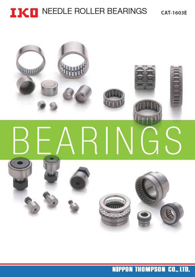
NEEDNLE ERDOLLEL RERO LBLEEARR BINEGASRINGCSAT-160C3EAT-1603E
BBEEAARRI NI NGGSS
Recognizing that conRsecrvoagtnioizni nogf tthaet gclonbsael rveantvioiron nomf etnhte isg lobal env•ir oTnhmee snpt eisc ification•s Tahned sdpimeceinfisciaotniosn osf apnrodd duimctes nins iothnis ocaf tparlodgu acrtes sinu bthjeisc tc taot aclohagn agre wsuitbhjoeuct ptor iochr ange without prior
the top-priority challetnhgee tofopr- pthrieo rwityo rcldh’asl lepnogpeu lafotiro nth, eN wipoproldn’ s population,o Ntiicpep.on notice.
Thompson will conducTth oitms pacstoivni twieisll wcoitnhd cuocnt sitids earcativointi eosf wthieth consider•a tWionh eonf tthhee se prod•u cWtsh eanre t hexepseo rpterodd, uthcets e axrpeo ertxepro srhteodu,l dth ceo enxfiprmor tae rfo srhwoaurldi ncgo ncfoirumn tary f oarnwda ard uinsge, caonudn, try and a use, and,
environment as a coerpnovriraoten mseoncti aal sr eas pcoonrspiboirlaittye, rseodcuiacle reitsp onsibility, reduce its
negative impact on thne geantiviero nimmpeanctt, oand t hhee lepn fvoirsotnemr ean rti,c ha nd help fositne rc aa sreic h o f falling uinnd cear sthe e ocfu fsatlolinmge ur'nsd rerq tuhiree cmuesntotsm, teark'se rneeqcueirsesmaeryn tpsr,o tcaekdeu nresc essuscahr ya sp reoxcpeodrut res such as export
global environment. global environment. permission applicaptieornm. ission application.
• Although all data •in A tlhthiso ucgahta alollg d haatas ibne tehnis c caaretafulollgy hcaosm bpeilend ctoa rmefauklley tchoem inpfiolerdm taot iomna kaes cthoem inpfloetrem asti on as complete as
ISO 9001 & 1IS4O00 910 Q01u a&l i1ty4 0s0y1s tQemua lity sypsotsesibmle, NIPPON pTHosOsMibPleS, ONNIP PCON., LTTHDO. MshPaSllO nNo tC bOe .l,i aLbTlDe. fsohr alnl yn odta bmea lgiaebsl ew fhoar tasnoye vdearm, dairgeecst worh atsoever, direct or
indirect, based upoind airneyc tin, fboarmseadt iuopn oin tahnisy cinaftoarlmoga.t iNonIP iPnO thNis T cHaOtaMloPgS. ONNIP PCON., LTTHDO. MmPaSkeOsN n Co O., LTD. makes no
registrationr ceegristitfircaatitoen certificatewarranty, either expwraersrsa notry i,m epithiledr ,e ixnpcrleusdsin ogr tihmep iimlepdi,l eindc wluadrirnagn tyh eo fi mpeirlecdh awnatarrbainlity orf fmitneercshsa fnotra ab ility or fitness for a
particular purpose.particular purpose.
• Reproduction and• cRoenpvroerdsuiocnti owni tahnodu tc poenrvmerissioionn w airteh opurto hpiebrimteids.sion are prohibited.
NEEDLE ROLLER BEARINGS CAT-1603E
NEEDLE ROLLER BEARINGS CAT-1603E
Page2
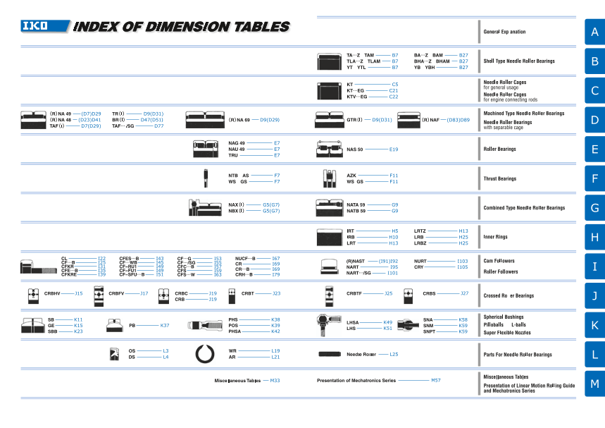
INDEX OF DIMENSION TABLES
(D83)D89
D29 D77
CL I22 CFES…B I43 CF…G I53 NUCF…B I67
CF…B I25 CF…WB I45 CF…/SG I55 I69 (R)NAST (I91)I92 NURT I103
CFKR I31 CF-RU1 I49 CFC… I57 CR
B
CFS 59 CR…B I69 NART I95 CRY I105
CFE…B I35 CF-FU1 I49 I
CFKRE I39 CF-SFU…B I51 CFS…W I63 CRH…B I79 NART…/SG I101
CRBHV J15 CRBFV J17 CRBC J19 CRBT J23 CRBTF J25 CRBS J27
CRB J19
SB K11 PHS K38 K49 SNA K58
GE K15 PB K37 POS K39 LHSA
LHS K51 SNM K59
SBB K23 PHSA K42 SNPT K59
M57
Page3
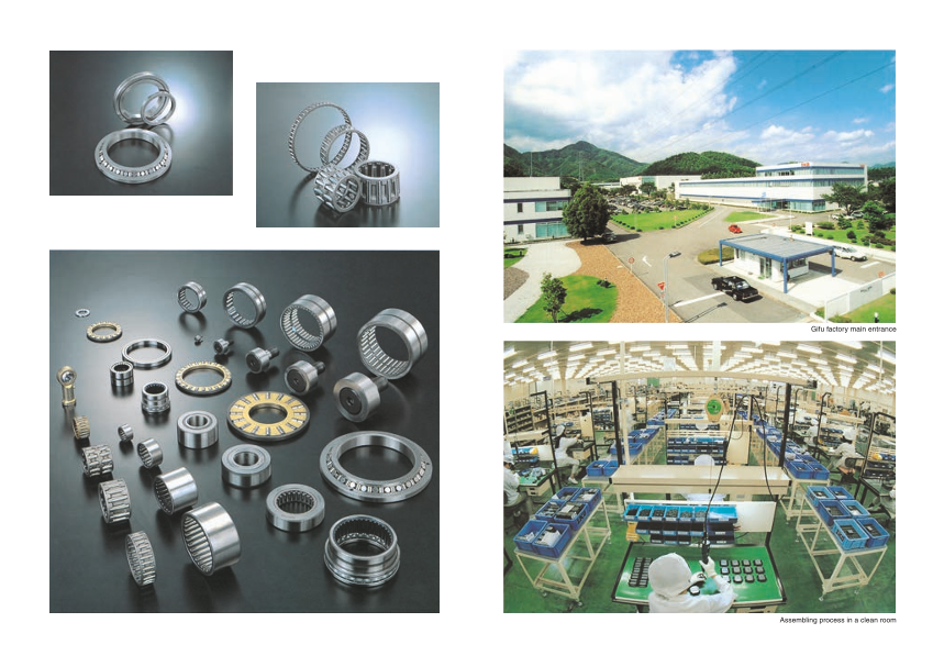
Gifu factory main entrance
Assembling process in a clean room
Page4
CAT-1603E
The IKO Needle Roller Bearing Series are manufactured through a control system that alleviates
their impact on the global environment to meet the quality requirements of ISO 14001 in
compliance with the quality requirements level of ISO 9001 for quality improvement.
The standard products listed in this catalog comply with the specifications of the ten hazardous
materials mentioned cited in the European RoHS Directive.
In the table of dimensions, standard products are referred to using identification numbers marked with .
The products are reputed for high quality, reasonable price and quick delivery. The identification numbers marked
with refer to our semi-standard products.
The specifications and dimensions of products in this catalogue are subject to change without prior notice.
1
Page5
Index
A
B
General Explanation Description of Each Series & Table of Dimensions C
Characteristics of Needle Roller Bearings A 3 Shell Type Needle Roller Bearings TA・TLA・BA・BHA B 1
Types and Features of Bearings A 5 Needle Roller Cages for general usage KT・KT…N C 1 D
Outline of Bearing Selection A 16 Needle Roller Cages for engine connecting rods KT…EG・KTV…EG C 17
Basic Dynamic Load Rating and Life A 17 Machined Type Needle Roller Bearings NA・TAFI・TRI・BRI D 1
Basic Static Load Rating and Static Safety Factor A 21 C-Lube Machined Type Needle Roller Bearings TAF…/SG D 75 E
Calculation of Bearing Loads A 22 Needle Roller Bearings with separable cage NAF D 79
Boundary Dimensions and Identi cation Number A 26 Roller Bearings NAG・NAU・TRU・NAS E 1
Accuracy A 30 Thrust Bearings NTB・AS・AZK・ F
WS・GS F 1
Clearance A 37 Combined Type Needle Roller Bearings NAX・NBX・NATA・NATB G 1
Fit A 39 Inner Rings IRT・IRB・LRT・LRB H 1 G
Design of Shaft and Housing A 44 Cam Followers CF…B・CFKR・CFS・NUCF…B・CR…B・CR I 1
Lubrication A 49 C-Lube Cam Followers CF…/SG I 55
Friction and Allowable Rotational Speed A 56 Short Stud Type Cam Followers CFC…B I 57 H
Operating Temperature Range A 57 Roller Followers NAST・NART・NURT・CRY I 83
Handling of Bearings A 57 C-Lube Roller Followers NART…/SG I101
Crossed Roller Bearings CRBHV・CRBFV・CRBC・CRB・CRBT・CRBTF・CRBS J 1 I
Spherical Bushings SB・GE・SBB K 1
Pilloballs PB・PHS・POS・PHSA K 29 J
L-balls LHSA・LHS K 45
Super Flexible Nozzles SNA・SNM・SNPT K 55
Parts For Needle Roller Bearings OS・DS・WR・AR・Needle Roller L 1 K
Miscellaneous Tables M33 L
Alphabetical Index M59 M
2 3
Page6
General Explanation
Nippon Thompson Co., Ltd. is a bearing
manufacturer that launched the technical
development of needle roller bearings for the
first time in Japan and is proud of the high
quality level and abundant varieties of its
products.
Needle roller bearings are bearings for rotary
motion that incorporate needle- shaped thin
rollers instead of ordinary bearing balls or
rollers. Compared with other rolling
bearings, they are small-sized and
lightweight but have a large load capacity.
They are widely used with high reliability in
the fields of automobiles, industrial machin-
ery, OA equipment, etc. as resource-saving
type bearings that make the whole machine
compact.
A1 A2
Page7
Characteristics of Needle Roller Bearings
CharaCchteariascttiecsri sotfi cNse oefd Nlee Redolele Rr oBlelear iBnegasrings A
Bearings cBaena rbineg csl acsasnif ibeed cinlatos stiwfieod m ination ttwypoe ms,a nina mtyepley sr,o nllianmg e lbye raorlilninggs abneda rsinligdsin ga nbde aslriidnignsg. b Reaorlliings b. e Raorilnlignsg bearings
can be sucbadniv ibde ds ufubrdtihveidr eindt ofu brtahlel br einatori nbgasll abneda rionlglesr abneda rrionlglesr abcecaorridnignsg atocc tohred irnogll intog tehlee mroellinntgs. elements. ClassifiCcalatisosnif oicfa btieoanr ionfg bsearings
IKO NeedIleK OR oNlleer dBle aRroinllgesr aBrea hriingghs-p arerec ihsiognh -rporlelicnigs iobne arroilnlignsg wbeitha rain g lso ww isthe cati o lnoawl hseicgthiotn, ainl choeripgohrta, tiincgo nrpeoerdaltein g needle B
rollers as trhoelle rrosl liansg tehlee mroellinntg. T ehlemy heanvt.e T thheey fohlalovwe itnhge ffeoalltouwreinsg. features.
Deep grooveD beaelpl bgeroaorivneg sball bearings C
Merit sM oefr Ritos lolifn gR oBlelianrgi nBgesarings Merit s Mofe Nritese odfle N Reoeldleler BReoallerirn Bgsearings Angular conAtancgtu blarll cboenatraincgt sball bearings
Radial baRlal dial ball
bearingsbearingsSelf-aligningS belafl-la blieganriinngg sball bearings
ComparedC owmitpha rseldid inwgit hb esalirdininggs , breoallriinngg sb, eraorlilninggs bearinCgos mparedC owmithp aorethde rw irtohl liontgh ebre arorilnlinggs , bIeKaOr inNgese, dIlKeO Needle D
have the fohlalovwe itnhge mfoellroitwsi:ng merits: Roller BeaRrionlglesr hBaevaer itnhges fohlalovwe itnhge afodlvloawntinag easd:vantages: Others Others
With a low sectional height, they can Thrust ball bTeharruinsgt sb awlli tbhe falaritn bgasc wk iftahc felat back face
Stati c a nSdta kticn eatnicd fkriicnteiotinc ifsri clotiwo.n is low. With a low sect onal ight, they can
with s t a nwdi thesatavny dlo haedasv.y loads. E
Thrust bTalhlrust balTlhrust ball bTeharruinsgt sb awlli tbhe alriignngisn gw siteha at lwigansinhger seat washer
Since theS indcifefe rethnec ed ibffertewneceen bsetatwtice efnr icstitoanti c anfrdic tion aSnidn ce theSy inhcaev et hae yl ohwa vsee cat iolonwal sheecigtihotn aclo mhepigahret dc ompared bearingsbearings
kinetic fricktionne tisc sfrmicatioll na nisd stmhea lflr iacntido nthael cforiecftfiiocnieanl tc iose fficientw isit h otherw irtohl liontgh ebr eraorlilninggs baenadr inygest caannd wyietht sctand withstand Double-direcDtoiounb alen-gduirleacrt icoonn atancgtu tlharru csot nbtaalcl tb teharruinsgt sball bearings
also smalal,l sdor ivsem aulnl, itsd riovre munaictsh inoers mcacnh ibne s mcaadne be mahdea vy loahdes,a vmya lcohaidnse,s mcanch binee ms acadne bmeo rme acdoem mpaocret compact Others Others
more commpaocret acnodm lpigahcttw aenigdh lti,g shatwvienig hmt,a scahvinineg cmosatcsh ine cosatnsd lightwaenigdh lti,g thhtuwse isgahvti,n tgh ucso stasv. ing costs. F
and powera ncodn psouwmepr tcioonn.sumption.
Needle rolleNr beedarlein rgosller bearings
Stab l e a Sctcaubrlaec ayc ccaunr abcey mcanin btaei nmeadintained Rota t i n g R tootraqtuineg i sto srqmuaell ,i sim spmraolvl,i nimg proving Cylindrical rColylelirn dbreiacrailn rgosller bearings G
for lo n g fpoer rlioondgs .periods. mec h a n miceacl hefafinciiceanlc eyf.ficiency. Radial roRllaedrial roller
bearingsbearingsTapered rolleTra pberaerdin rgosller bearings
Owing toO wleinsgs wtoe alre, sss tawbelea r, acsctaubralec y accaunr abcye can Sbein ce the Srointactein tgh era rdoituasti nisg srmadailul,s t hise s rmotaltli,n tgh eto rroqtuaeti ng torque
maintainemd afoinr tlaoinnge dp eforiro ldosn.g periods. is also smisa lal lsuon dsemr athll eu nsdaemre t hfreic tsioanmael cfroicntdioitnioanl sc, onditions, Self-aligningS reolfl-laelri gbneianrgin rgosller bearings
thus improthviunsg impercohvaingic aml ecffhicaineinccayl. efficiency.
Others Others H
Mach i n eM raeclihaibnieli trye liisa bimiliptyro ivse idm. proved. Inert i a i sIn meritniaim isiz medin. imized. Thrust needTleh roulslet rn beedarlein rgosller bearings
Since theS binecaer inthge lifbee acraing bleif ee sctaimn abted ebsatimseadte odn b ased Soinn ce the Sbienaceri ntgh ev obleuamrien ga nvdo luwmeieg hatn adr ew esmighatll ,a trhee s mall, the Thrust cylindTrhircuasl tr oclylelirn dbreiacrailn rgosller bearings I
Thrust roTlhlerrust roller
rolling fatigroulelin, gm faacthiginue, rmeliaacbhiliintye irse ilmiabpirloitvye ids .improved. moment omf ionmeretinat off tihne rbtieaa orifn tgh eis b meainriimngiz iesd m winhiemni zite d when it bearingsbearings
is put in miso tpiount .in motion. Thrust taperTehdr urosltl etra pberaerdin rgosller bearings
Others Others J
Lubr i c a tLiounb riisc astiimonp lisfi esdim. plified. Most s u Miteods t os uoistecdil ltaot ionsgc milloatiionngs m. otions.
Since greSasinec elu bgrriecastieo nlu ibsr iscuaftfiiocnie nist isnu fmficoiestn tc ains emso, st caseMsa, ny rollMinagn ye leromlleinngts ealerme eanrtrsa nagred aarrta nag esdm aaltl a small
lubricationlu cbarnic abteio snim capnlif ibeed sfoimr epalifsieyd m foarin eteansay nmcea.intenance.spacing pistcpha,c ainngd p tihtcish ,c oanfdig tuhrisa tcioonn fiisg umroastito snu iiste md otos t suited to Metals, busMhientgasls, , o bthuesrhsings, others K
oscillatingo mscoitlliaotnins.g motions.
L
M
A3 A4
Bearings
Bearings
Sliding bearings Rolling bearings
Sliding bearings Rolling bearings
Roller bearings Ball bearings
Roller bearings Ball bearings
Page8
Types and Features of Bearings
TypesT yapneds F aenadtu Freas toufr eBse oafr iBnegasrings A
IKO BearinIKgOs cBaena brien gros ucgahnly b cel arsosuigfiehdly icnltaos rsaifdieiadl ibnetoa riandgisa la bneda trhinrgus t abneda rthinrgus ta bcecaoridnignsg atoc caoprpdliincga btole alopapdlic daibrelec tlioand. direction. Crossed RCorlolesrs Bede aRrionlglesr aBrea sripnegcsi aal rseh sappeec biael asrhinagpse tbheaat rcinagns s timhautl tcaanne osiumsulyl traenceeoivues llyo aredcse iinv ea llo daidresc itnio anlsl dwiriethc taio ns with a
Radial BeaRraindgiasl aBrea grirnogusp eadre i ngtroo uSpheedll iTnytop eS Nhelel dTlyep eR oNlleer dBle aRrionlglesr, BMeaacrhiningesd, MTyapceh inNeede dTlyep eR oNlleer dBle aRrionlglesr, Baenadr ings, and single beasriingl.e bearing.
various othvearr itoyupse so.t h Tehr rtuyspte Bse. aTrhinrgus ta Bre agrrionugpse adr ein gtoro Tuhpreuds ti nNtoe eTdhlreu Rsto Nllere Bdlea Rrinogllesr a Bneda Trihnrguss ta Rndo lTlehrr Buseta Rrinogllesr. Bearings. Bearings oBtehaerri nthgas no trhoellirn tgh abne arorilnlignsg, bseuacrhi nagss ,s seulfc-ahl igans insge lfS-aplhigenrincagl SBpuhsehriincgasl Bthuasth cinagns s tuhpapt ocrat nr asduiaplp loorat drsa daianld l oads and
Follower BFeoalrloinwgesr tBhaeta rainreg su stheadt faore c uasme dm feocr hcaanmis mse cahnadn liisnmeasr amndo tiloinne ar em gortoiounp eadre i ngtoro Cupaemd Finotollo Cwaemrs Faonldlo Rwoelrlse ra nd Roller axial loadsa xainadl l oPaILdLsO aBnAd LPLIsL LaOndB AL-LBLasl lasn tdh aLt- Baraell su stheadt faore l inuks emde fochr alinkis mse,c ahraen aislmsos ,a avareil aablsleo. available. B
Followers.Followers.
ClassifiCcalatisosnif oicfa t i o n o Bf e a r i n g Bsearings C
TA, TAM TA, TAM CF…B, CFCKFR…B, CFKR
TLA, TLAMTLA, TLAM CFE…B, CFFKER…EB, CFKRE
BA, BAM BA, BAM CFES…BCFES…B
Shell Type BHA, BHABMHA, BHAM CF…WB D
Shell Type CF…WB
Needle RollNere eBdelaer iRnoglsler Bearings YT YT CF-RU1, CCFF-F-RUU11, CF-FU1
YTL YTL CF-SFU…CBF-SFU…B
YB YB E
YBH YBH
KT, KT…NKT, KT…N
Needle Roller NCeaegdelse fRoor lGleer nCeargael Us sfoarg Geeneral Usage
KTW KTW
Needle RollNere eCdalgee Rsoller Cages
KT…EG KT…EG NUCF…BNUCF…B F
Needle Roller NCeaegdelse fRoor lElenrg Cinaeg eCso nfonre Ecntignign eR oCdosnnecting Rods
KTV…EG KTV…EG CR, CR…BC, RC,R CHR…B, CRH
NAST, RNNAASSTT, RNAST
NA, RNA NA, RNA NART, CRNYART, CRY G
TAFI, TAFTAFI, TAF
TRI, TR TRI, TR NURT NURT
BRI, BR BRI, BR
Machined TMypaec hined Type
Needle RollNere eBdelaer iRnoglsler Bearings GTRI, GTRGTRI, GTR High Rigidity THyipgeh CRriogsidsietyd T Ryoplele Cr rBoesasreindg Rso (lVle)r Bearings (VC) RBHV CRBHV H
Mounting HoleMdo Tuynptein Hg iHgho lRedig Tidyiptye High Rigidity
C-Lube MachiCne-Ldu Tbyep Me aNceheindeled R Toypller NBeeadrilneg Rsoller BearingTsAF… /SGTAF… /SG Crossed RolleCr rBoesasreindg Rso (lVle)r Bearings (V) CRBFV CRBFV
NAF, RNANFAF, RNAF CRBC, CRCBRBC, CRB
Needle Roller NBeeeadrilneg Rso wlleithr BSeeaprainragbs lew iCtha Sgeparable Cage
NAFW, RNNAAFFWW, RNAFW I
NAU NAU Mounting Holed TMyopuen Stinugp eHr oSlelimd T Cyproes Sseudp eRro Sllelimr B Ceraorsinsgesd Roller BeariCngRs BTF CRBTF
NAG NAG
Roller BeariRnoglsler Bearings
TRU TRU
Roller BearingRso floler rS Bhearvinegss for Sheaves NAS NAS J
Thrust NeedTlher Rusotl lNere eBdelaer iRnoglsler Bearings NTB NTB
Thrust RolleTrh Bruesatr iRnoglsler Bearings AZK, AZ AZK, AZ K
with Thrust Bawlli tBhe Tahrirnugst Ball Bearing NAXI, NAXNAXI, NAX
Combined TCyopme bined Type with Thrust Rowlliethr BTeharurisntg Roller Bearing NBXI, NBXNBXI, NBX L
Needle RollNere eBdelaer iRnoglsler Bearings with Angular Cwointhta Acnt gBualall rB Ceoanritnagct Ball Bearing NATA NATA
with Three-poiwnitt hC Tonhtraecet- pBoailnl tB Ceoanritnagct Ball Bearing NATB NATB
M
A5 A6
Combined Type Thrust
Bearings Bearings Radial Bearings
Combined Type Thrust
Bearings Bearings Radial Bearings
Page9
A
Shell TySphee Nll eTeydple NReoelldelre B Reoalrlienrg Bsearings MachineMda Tcyhpinee Nde Teydple NReoelldelre B Reoalrlienrg Bsearings B
Shell Type SNheeelld Tley pReo Nlleere Bdlea rRinogllse r aBree alirginhgtws eaigreh t liwghithtw eight with Machined TMyapceh iNneedd Tley pRe oNlleere dBlea rRinogllse r hBaevea rianng so uhtaevre an outer
the lowest stheec tliownaels ht esiegchttio anmalo hnegi gnhete admleo rnogll enre beedaleri nroglsle r bearings ring made rbinyg mmaacdhein ibnyg , mhaecaht intrienagt,m heenatt, tarenadt mgreindt,i nagn. d grinding.
with outer rwinitgh, obuetcear ursineg t,h beeyc eamuspelo tyh eay sehmelpl ltoyyp ea osuhtelrl type outer The outer rTinhge hoaust esrt aribnlge haigsh srtiagbidleit yh iagnhd r icgaidni tby ea neda scilayn be easily
ring mader infrgo mm ad eth ifnro msp eac iathl-isnt esepl epcliatle-s tewehli cphl aitse which is used even fuosre lidg hetv aelnlo fyo rh loiguhsti nagllso.y housings.
accurately darcacwunra, tcealyr bdurraizwend, caanrdb uqruizeendc haendd. quenched. These beaTrhinegsse abrea rainvgasila balree ina vavialariboleu s int ypveasri oauns d types and C
Since theseS binecaer itnhgess ea rbee parreinsgss-f iattered pinretos sth-feitt ehdo uinstion gt,h neo h ousing, no optimally soepletimctabllyle sfeolre cdtaiffbelere nfot r codnifdfeitrieonts csouncdhit ioanss such as
axial positioanxiinagl pfioxstuitrioens inagre f irxetuqrueirse da.r e T rheeqyu iarered . id Tehael yfo ar re ideal for heavy loadsh,e haivgyh -losapdese,d h riogtha-tsiopne eadn dro ltoawtio-snp eaend rlowta-tsiopne.e d rotation.
use in massu-sper oind umcaesds a-prtriocdleusc tehda ta retiqclueisre t heacto rneoqmuiyr.e economy. They are mTohset ys uaitraeb mleo fsotr sgueitnaebrlael -fpour rgpeonser alp-pulircpaotisoen sa.pplications.
D
Radial BeaRriandgisal BearPinagse B1 Page B1 Radial BeaRriandgial BeaPriange D1 Page D1
E
Needle NReoelldelre C Raoglelesr fCora gGeesn feorra lG Uesnaegrael Usage Needle NReoelldelre B Reoalrlienrg Bse wairtihn gSse wpaitrha bSlep Caaragbele Cage
Needle RoNlleere dClea gReso llfeorr CGaegneesr aflo rU sGaegnee rarle Ubseaagrein gasre bearings In Needle IRn oNllere dBle aRrinogllesr wBiteha rSinegpsa rwaibthle SCeapgaer,a bthlee Cage, the F
that displatyh aet xcdeisllpelnaty reoxtacteiollennatl proetrafotiormnaln cpee. rf oTrmheainr ce. Their inner ring,i nonuetre rr inrign,g oauntedr Nrinege dlaen dR oNlleer dClea gReo lalerre Cage are
specially shsappeecdia lclya gsehsa pweidth chaigehs riwgitdhit yh iagnhd r iagcidciutyr aacny,d accuracy, combined, caonmd bthineeyd ,c an db eth esye pcaarna tebde esaespialyr.a tTedh ise atyspilye. This type
precisely gupirdeec itshel yn geueidle trhoelle nrse.edle rollers. has a simphlea ss taru scitmurpel ew sitthru hcitguhre awccituhr ahcigy.h aInc caudradcityio. n ,I n addition,
Since needSlein creo llenrese dwleit hr oellxetrse mweitlyh semxtarellm deilmy esnmsiaolnl adl imensional the radial ctlheea rraandciael ccalena rbaen cfre eclay ns eble cftrede lyb ys eclheocotesdin gby choosing
variations vina rdiaiatimonest eirn adreia minectoerrp oaraet eind coarnpdo rraetteadin eadn,d retained, an assemblayn c aosmsbeimnabtliyo nc.ombination. G
Needle RoNlleere dClaeg Reso llfeorr CGaegneesr aflo rU sGaegnee raarle Uussaegfeu l ainre useful in These beaTrihnegse h baevea rienxgcse lhleanvte roetxactieolnleanl t preortafotriomnanl cpee, rformance,
small spacsems awllh sepna ceosm bwinhedn wcoitmh bsinheadfts waitnhd shoauftsi nagn d housing because Nebedclaeu Rseo lNleer eCdaleg eRso allreer uCsaegde.s are used.
bores that baorree sh ethaat t traeraet ehde atn dtr eaactecudr aatnedly agcrocunradt ealys ground as
raceway surafacceewsa.y surfaces. H
Radial BeaRriandgial BeaPriange C1 Page C1 Radial BeaRriandgial BePaarigneg D79 Page D79
I
Needle NReoelldelre C Raoglelesr fCora gEensg ifnoer ECnogninec Ctionngn Reocdtisng Rods Roller BReoalrlienrg Bsearings
Needle RoNlleere Gdlaeg Reso llfeorr GEangeinse foCro nEnegcintien gC Ronondesc atinreg Rods are Roller BeaRrionlglesr, Bine awrhinicghs , roinl lewrsh icahre roinllceorsrp oaraet eindc oinr porated in
used for muosteodr cfoycr lemso, tosmr cayllc mleso,t osrm vaelhl imcleosto, ro vuetbhoicalerds , outboard double rowds,o uabrele nronw-s,e paarera nbolen -hseapvayr-adbulety hbeeaavryin-dgust.y bearings. J
marines, snmoawr inmeosb, ilsenso, wg emnoebraille-ps,u rgpeonseer ael-npguinrpeoss, eh iegnhg- ines, high- They can wTithhesyta cnadn nwoitt hosntalyn rda dnioatl olonalyd sr abduiat la lxoiadl slo baudts axial loads
speed coms peresds ocros,m pertecs. stohrast, aertce. othpaetr aaterde uonpdeerar ted under as well, whiacsh waerell ,s wuphpicohr taerde astu tphpeo crtoendt aactt sth bee ctowneteanc ttsh bee tween the
extremely sexvtererem aenlyd sceovmerpel eaxn do pceormatpinlegx c opnedritaiotinsg scuocnhd itions such shoulders osfh ionunledre rasn odf oinunteerr rainngds oauntedr thrien gesn adn fda ctehse oefn d faces of
as heavy sahso chke alovayd sh, ohcigkh l osapdese,d hsi,g hi gshp etemdsp,e hraigthu retesm, peratures, rollers. Therorellfeorrse. , Tthheeyr eaforere m, tohsety s auritea bmleo sfot rs usitea balet tfhoer use at the
and stringeannt dlu sbtriicnagteionnt .lubrication. fixing side ofifx ain sgh saidft.e of a shaft. K
Needle RoNlleere dClaeg Reso llfeor CEangeinse foCro nEnegcintien gC Ronondesc tainreg Rods are
lightweight liagnhdtw heaigvhet haignhd lhoavde rhaitginhg slo adn dr ahtingghs r iagniddit yh igh rigidity
as well as sausp wereioll ra wse saurp rersioisrt awnecaer. resistance.
L
Radial BeaRriandgial BePaarigneg C17 Page C17 Radial BeaRriandgial BearPinage E1 Page E1
M
A7 A8
Page10
A
Thrust TBheraursint gBsearings Cam FoClalomw eFrosllowers B
Thrust BeTahrirnugsst cBoenasrisntg so f cao npsriestc iosef lya mpraedceis eclay gme aadned cage and Cam FolloCwaemrs Faorlelo wbearsr inagrse wbeitahr ian gst uwdi thin cao rsptourda tincgo rporating
rollers, anrdo llcearsn, raencde ivcea na xreiacle liovea dasx. ia Tl hloeayd sh.a v eT hheiyg hh ave high needle rollneerse dinle a r othlliecrks wina lale tdh iocku twera rlliendg .outer ring.
rigidity anrdig ihdigtyh alonadd hcigahp alcoiatide sc apnadc ictiaens baen du sceadn ibne used in They are dTehseiyg naered dfoers oigunterd rfionrg oruoteart iorin,g a rnodta thioen ,o uatnedr the outer
small spacsemsa. ll spaces. rings run drirnegcst lyru onn d mireactitnlyg ocna m agtuinidge c saumrf agcueidse. surfaces.
Thrust NeTehdrleu sRt oNlleer dBl e aRrionlglesr uBseea rninegesd lues reo lnleeres,d lwe hriolellers, while Various tyVpaersi ooufs C taypme sF olflo Cwaemrs Faorell oawvearisla balre. a Tvhaeilay balere. They are C
Thrust RolTlehrr uBseta Rrionlglesr uBseea criynlginsd uriscea l cryollilnedrsr.ical rollers. widely usewdid aesly foulsloewd ear sb efoallroinwgesr fboer acrainmgs mfoerc hcanmis mse chanisms
and for lineaanrd m foort iloinnesa.r motions.
D
Thrust BeTahrirnugst BeariPnagge F1 Page F1 Follower BFoelaloriwnger BearPinage I1 Page I1
E
CombinCeodm Tbyinped N Teyepdele N Reoeldleler BReoallreirn gBsearings Roller FRollloewr eFrosllowers
CombineCd omTybpinee dN eTeydplee NReoelldelre BReoalrleinrg sB eaarrein gs are Roller FollRowolelersr Faorell obweearrsin agrse inb ewahriincghs n iene wdlhei crho lnleerse dalere r ollers are F
combinatiocnosm boifn at iorandsi aol f bae arraindgia la nbde aari ntgh ruasntd bae atrhinrugs. t bearing. incorporatiendc oinr pao trhaitcekd wina lale tdh iocku twera rlliendg .outer ring.
Caged NCeeadgled RNoellerd leB eRaorilnlegrs Baerea rinugsse d araes ursaeddia l as radial These beaTrhinegsse abrea driensgisg naerde fdoer soigunterd rfinogr oroutaetri ornin,g a rnodta tion, and
bearings baenadr inTghsr usatn dB aTlhl rBuseta rBinaglls Boer aTrihnrguss t orR oTlhlerru st Roller the outer rtihneg so ruutenr d rirnegcstl yru onn d mireactitnlyg ocna m agtuinidge c saumrf agcueidse. surfaces.
Bearings aBrea ursinegds a asr eth urusestd b aesa trhinrgus.t bearings. They are uTsheedy aasr efo ullsoewde ra sb efoalrloinwgesr fobre acarimng sm feocrh caanmis mse chanisms
They can Tbhee ys ucbajne cbteed stuob rjeacdtieadl lotoa dras daianl dl oaaxdias l alonadd sa xial loads and for lineaanrd m foort iloinnesa.r motions. G
simultaneosuimsluy.ltaneously.
H
CombinedC oTympbei nBeda rTiynpge BeaPraingge G1 Page G1 Follower BFoelaloriwnger BeaPraingge I83Page I83
I
Inner RIninngesr Rings CrosseCdr oRsoslledr BReoallreinr gBsearings
Inner RingIsn naerer Rheinagts-t raeraet ehde atn-tdre fiantiesdh eadn db yfi ngirsinhdeidn gb yto g ari nding to a Crossed RCorollesrs eBde aRroinllgesr Bareea rhinigghs- raigried ithyi gahn-rdig icdoitmy paancdt compact
high degreheig ohf daecgcruerea coyf ancdcu ararec yu saend faorre N uesedl ef oRr oNlleer dle Roller bearings wbeitha ritnhgesir wcyitlhin dthrieciar l cryolilnledrrsi callt erronllaetresl ya lcterorsnsaetedl y crossed J
Bearings. Bearings. at right anagt lerisg htto aenagclehs o toh eer abceht woetheenr ibnentewr eaend inonueter r and outer
In the caIsne tohfe Nceaesdel eo fR Nolelerd lBe eRaroinllegrs , Bneoarrminaglsly, nthoer mally the rings. A sringsle. CAr ossinsegdle RCorlolesrs eBde aRroinllge rc aBne atraikneg lcoaand sta ke loads
shafts are shheaafts-t raeraet ehde atn-tdre fiantiesdh eadn db yfi ngirsinhdeidn gb ya ngdri nudsiendg and used from any fdroirmec taionnys dairte cthtieo nsa mate thtiem es asmuec ht imase rsaudciahl , as radial,
as racewaays s ruarcfaecweasy. sHuorfwaceeves.r , Hwohwene viet ri,s wimhepno sist iibsl eim top ossible to thrust, andth mruosmt, eanntd lo madosm.ent loads.
make shamft askuerf ascheasft ascucrofarcdeinsg atcoc othrdei nsgp etoci ftiehde suprefacicfie d surface These beaTrhinegsse abrea wrinidgesl ya rues ewdi dienl yt hues erodt aintin tgh ep arorttsa toinfg parts of K
hardness ohra srdunrfeascse orro usugrhfancees sr,o Iungnhenr eRsisn,g Isn naerer Rusinegds. are used. industrial rinodbuoststr, iaml arochbiontes , tomoalsc,h mine dtiocoalls e, qmueipdmiceanl te, qeuticp. ment, etc.
which reqwuhiriech croemqpuaircet nceosms, pahcigtnhe srsig, idhitiyg h anridg idhitiyg h and high
rotational aroctcautiroancay.l accuracy.
L
ComponeCnot mpaprotnent pPargte H1 Page H1 Crossed RCorollessr eBde Raroinllger BearPinage J1 Page J1
M
A9 A10
Page11
A
SphericSaplh Beurischailn Bgusshings Seals fSore aNlese fdolre N Reoeldleler BReoallreinr gBsearings B
Spherical SBpuhsehriicnagls Baurseh inseglsf -aalirgen inseg lf-saplihgenriincga l splhaeinr ical plain Seals for SNeeaelds lefo rR oNlleer dBlee aRroinllgesr Bhaevaeri nag slo wha vse cati olnoawl sectional
bushings, buwshiicnhg s,h awveh icihn nehra vea ndin noeur tear ndri ngosu tewr ithri ngs with height andh ecigohnts iasnt do fc oan sihset eot f mae tsahl ereint gm aentadl rsipnegc ianl d special
spherical slpidhienrgic saul rsfalidciensg. sTuhrfeayc ecsa.n Ttahkeey ac alanr gtaek era ad ialal rge radial synthetic rsuybnbtehre.tic rubber.
load and alo bai-dd airencdt iao nbai-ld airxeicatli olonaadl axt itahle lo saadm aet tihmee s.ame time. As these sAesa tlsh easre smeanlsu farcet umreadn utofa tchteu resda mtoe tshec tsioanmael sectional
They are Thdeivyid eadre indtiov idsetede li-notno- ssteteel l-toynp-esste ethl atty paerse that are height as hNeeigehdtl ea sR oNlleer dBlee aRroinllgesr, Bgereaarisneg sl,e agkraeagsee a lneda kage and C
suitable fosru aitpapbliec afotior nasp pwlihcearteio nthse wreh eare tahlteerren atre laolatedrsn ate loads the penettrhaeti opne noef trfoarteioignn o pf afortriecilgens cpanrt icble se fcfeacnt ivbeel y effectively
or shock olro asdhso, cka nldo admsa, inatennda nmcaei-nfrteen antycpee-sfr ewe hticyhp es which preventedp rbevye nfitteindg btyh efimtti ndgi rethcetlmy tod irtehcetl ys itdoe st hoef sides of
require nor leuqburircea tnion l.ubrication. combinablceo bmebairninagbsle. bearings.
D
SphericalS Splhideirnicga Bl eSalirdiningg BearPinage K1 Page K1 ComponeCnot mPaprotnent PPaargte L1 Page L1
E
PILLOBPAILLLLOsBALLs Cir-clipCsi rf-ocrl iNpese fdolre N Reoeldleler BReoallreinr gBsearings
PILLOBALPLIsL LaOreB AcLoLmsp acret sceolmf-aplaigcnt insge lfs-aplhigenricnagl spplahienr ical plain Cir-clips foCr irN-celiepdsl efo Rr oNlleer dBle aRrionlglesr hBaevaer inbgese nh asvpe cbiaelelyn specially F
bushings wbuhsichhin cgasn w shuipchp ocrat na slaurpgpeo rat dai alal rlogaed r aadniadl alo baid- and a bi- designed dfoers ingenedl ef orro lnleere dblea rionlglesr obne awrihnigcsh , oin wmhaicnhy, in many
directionald airxeicatli olonadl axt iathl elo saadm aet thime es.ame time. cases, gencearsaellsy, agveanilearballely Caivr-aciliapbsl ec aCnirn-colti pbse cuasnendo. t Tbhee uys ed. They
PILLOBALPLI LRLoOdB EAnLdLs Rhoadv eE enidthse hr aav efe emitahler thar efeamda inle tthhere ad in the have a lowh asevec taio nloawl hseicgthiot naanld h aerigeh vte arnyd r iagride. very rigid.
body or a bmoadlye othr rae amda olen tthree abdo doyn, sthoe t hbeoyd yc,a sno b teh eeya csailyn be easily There are TChier-rceli pasr ef oCr isr-hcalipfts faonrd s hfoarf tbso arensd, faonr db othresy, aarned they are
assembleda sosnetom mbleadch oinetos .machines. used for puoseitdio nfoinr gp otos itpiorenvinegn tt ob eparerivnegn mt boevaerminegn tm ino vtehme ent in the G
PILLOBALPLIsL LaOreB uAsLeLds ianr eco unstreodl ainn dco lnintkro ml aencdh aliniks mse cinh anisms in axial direcatioxina.l direction.
machine tmooalcsh, intex ttioleo lsm, atcehxitniles ,m paacchkinaegsin, gp amcakcahginegs ,m achines,
etc. etc.
H
SphericalS Splhideirnicga Bl eSalirdiningg BeParaigneg K29Page K29 ComponeCnot mPaprotnentP Paagret L17Page L17
I
L-BallsL-Balls NeedleN Reoeldlelers Rollers
L-Balls areL -sBealfll-sa laigrnei nsge lrf-oadli-genidnsg crodn-seisntdinsg c ofn asi sstpinegc ioafl a special Needle RoNlleersd lea reR oullseerds aforre nuesedl ef orro lnleere bdelea rrionlglesr abneda rings and
zinc die-cazsint ca ldloiey- cbaosdty a allnoyd bao sdtyu dadnedd a b satlul dwdheicdh b haalls w ithsi ch has its are rigid aanrde h riighidly a ancdc uhrigahtely. accurate. J
axis at righatx-aisn agtl ersig thot -tahneg bleosd yto. the body. These neeTdhle sreo llneerse dalere rowlildeersly a ures ewdi daesl yr oullsinegd ealse mroellnintgs elements
They can Tpheerfyo rcma nti lptienrgf omrmov teilmtinegn tm aonvde mroetantti oann dw irtoht alotiwon with low for bearingfosr, abneda rainlsgos ,a asn pdi nasls aon ads s phianfsts a.nd shafts.
torque, antdo rtqraune,s manitd p torwanesr msimt poowthelyr dsumeo ototh tlhy ed uen iftor mth e uniform
clearance cbleatwraenecne t hbe tswliedeinng t hseu rsfalicdeinsg. surfaces.
They are Tuhseey d airne luinske dm ienc hliannki smse china naisumtosm oinb ilaeus,t omobiles, K
constructiocno nmstarucchtiinoenr ym, afacrhmin earnyd, fpaarmck aagnindg p macakcahgiinegs ,m achines,
etc. etc.
L
SphericalS Splhideirnicga Bl eSalirdiningg BeParaigneg K45Page K45 ComponeCnot mPaprotnentP Paagret L23Page L23
M
A11 A12
Page12
A
FeatureFse oaft u r e s oBf e a r i n gBsearings
Bearing serBieesaring series AppearanceAppeaDriarencctioen of DLiroeacdti odnir eocftion LoadA dlliorewcatbiolen Allowable
motion amnodt icoanpacity arnodt actaiopnaacl istypeedrotatioFnrailc stpioeen
Sectional Reference
d Frihcteiiogn
Sectional Reference
ht hepigahgte page Bearing serBieesaring series AppearanceAppeaDriarencctioen of DLiroeacdti odnir eocftion LoadA dlliorewcatbiolen Allowable
motion amnodt icoanpacity arnodt actaiopnaacl istypeedrotatioFnrailc stpioeen
Sectional Reference
d Frihcteiiogn
Sectional Reference
ht hepigahgte page B
Caged type Caged type Needle rollerN eedle roller
bearings bearings
Shell Type Shell Type Thrust Thrust
Needle RollNereedle Roller B1~ B1~ Bearings Bearings F1~ F1~
Bearings Bearings C
Full Full
complementcomplement Roller Roller
type type bearings bearings
D
For For With With
general usage neral usage C1~ C1~ thrust thrust
ball bearing ball bearing
Needle Needle
Roller CageRsoller Cages
For engine For engine With With E
connecting connecting C17~ C17~ thrust thrust
rods rods roller bearingroller bearing
Combined TCyopme bined Type
Needle RollNere edle Roller G1~ G1~
Bearings Bearings
With With F
Caged type Caged type angular angular
contact contact
ball bearing ball bearing
Machined TyMpaechined Type
Needle RollNereedle Roller D1~ D1~
Bearings Bearings
Full Full With With
complementcomplement three-point three-point G
type type contact contact
ball bearing ball bearing
Needle RollNereedle Roller
Bearings wiBthearingsC wagitehd type Caged type D79~ D79~ Caged type Caged type H
Separable CSaegpearable Cage
Cam FollowCearsm Followers I1~ I1~
Full Full
Caged type Caged type complementc omplement I
type type
Full Full
Roller BeariRnoglsler Becaorminpglesmentcomplement E1~ E1~ Separable Separable
type type caged type caged type J
For sheavesFor sheaves Roller FolloRwoelrlser FoNlloonw-seerpsarabNleo n-separable
caged type caged type I83~ I83~ K
Non-separabNleo n-separable
Symbol SymRobtaotlion RotatioOnscillating OsRcaildlaiatinl g RAadxial LighAt xial MeLdigiuhmt MHedaivuym EHsepaevcyi ally Especially
motion molotiaodn lolaodad loadload loaldoad loloaadd eloxacdellent exceEllxecnetllent ExcNelolermntal Normal full full
complementc omplement
type type L
M
A13 A14
Page13
Outline of Bearing Selection
Features of Bearings OutlinOeu otlfi nBee oafr iBnega Srienlge cStieolnection A
Features of Bearings
IKO BearinIKgOs aBrea arivnagisla balree ina vmaialanbyle t yinp ems aannyd tyspizeess .a nTdo soibzetasi.n Tsoa tiosbfatactino rys abtiesafarcintogr yp ebrefoarrminagn pce rfionr mancchein eins manadc hines and
Bearing serBieesaring series AppearanceAppeaDriarencctioen of DLiroeacdti odnir eocftion LoadA dlliorewcatbiolen Allowable
motion amnodt icoanpacity arnodt actaiopnaacl istypeedrotatioFnrailc stpioeen
Sectional Reference
d Frihcteiiogn
Sectional Reference
ht hepigahgte page equipmente, qitu isip emsesnetn, tiita ils t oe ssseelenctita tlh toe smeolesct ts tuhieta mbleo sbte sauriitnagb lbey b ceaarreinfugl lyb ys tcuadryeifnugll yt hsetu rdeyqiunigre tmhee nretsq ufoirre tmhe natpsp floicr athtioen a.pplication.
Although tAheltrheo uisg nho t hpearret icisu lnaor praorctiecduularre porro crueldeu froer obre raurlien gfo sre blecatrioinng, asenl ecxtaiomnp, laen o ef xaa cmopmlem oofn aly c aodmomptoendl yp raodcoepdtuerde procedure B
is shown inis t hsheo fiwgnu rien btheelo fwig.ure below.
Caged type,Caged type,
Separator tySpeparator type
An examApnl e xoafm pprolec eodf uprreo cfoerd buerea rfionrg b seealreicntgio snelection
C
Confirmation of ● Identify th●e mIdaecnhtifnye t haen dm palcahcien ew haenrde pthlaec eb ewahrienrge itsh eto b beea ruinsegd is. to be used.
Crossed CrosseFdu ll Full Confirmation of
Roller BeariRnoglsler Bceoamrpinlegmsentc omplement J1~ J1~ requiremreqnutsir eamnde nts and ● Confirm ●the C orenqfiurmire mtheen trse qfourir ebmeaernintsg sfo rs ubceha rainsg sre qsuicrehd abs eraerqinugir ed bearing
type type 1 1 performancep,e arfnodrm alnscoe ,c oannfdir ma lsthoe copnefiramti ntgh ec onpdeirtaiotinnsg acnodn dsitpioencsia la nd special
operatinogp ceorantdinitgio cnosnditions environmente cnovnirdointimonesn.t conditions.
D
● Select th●e bSeealericntg t htyep bee sauriitnagb ltey pfoer stuhieta obpl e rfaotri nthge operating
Slim type Slim type 2 2 conditions bcyo ncdointisoindse rbinyg c loonasdid deireincgti olona adn ddi rmecatgionni- a nd magni-
SelectioSne olef cbteioanri nogf btyepaering type See page See page
tude, rigidity,t ufrdicet,i oring,i dailtlyo,w fraicbtlieo nro, taltlioownabl lsep reoetadt,i obnealr isnpge ed, beariAng5 A5
space, etc. space, etc.
E
Steel-on-steeSlt eel-on-steel ● Select the● b eSaerliencgt dthime ebnesairoings bdyim ceanlcsuiolantsin bgy b ceaalcriunlga ting bearing
type type SelectioSne olef ction of See page
Spherical Spherical 3 3 load, life, staltoica ds,a lfiefety, sfatacttiocr ,s eatfec.ty factor, etc. See page
bearing bdeimareings idoinmsensions A17 A17
Bushings Bushings K1~ K1~
Maintenance-Mfreaein tenance-free F
type type ● Select the● a Sceculercatc yth ea sa rcecquurairceyd absy rtehqeu imreadc hbiyn et hoer machine or
4 Sele4ctioSne olef ction of equipment. equipment. See page See page
accuracay ccclausrasc, ey tcl.ass, etc. A30 A30
Insert type, Insert type, G
Lubrication tLyupberication type
● Select th●e Srealdeicatl tchlea rraandciael ccolenasridaenrcien g cothnes idfeitr, ing the fit,
5 Sele5ctioSne olef ction of temperature,t ermotpaetiroantuarle ,s preoetadt,io ninacll insapteioend , oifn cthlinea tinionne ro f theS ienen epra ge See page
radial clreaadraianl ccele aanradn fcite and fitand outer rinagnsd, eotuct.er rings, etc. A37 A37
PILLOBALLPsILLOBDAieL-Lcsasting tyDpie-, casting type,
Lubrication tyLpuebrication type K29~ K29~ H
6 Dete6rminDaettieornm oinf abteioanri nogf bdeimareings idoinms,e ancsciounrasc, ay,c rcaudriacl yc, lreaadraianl ccele aanradn fcite and fit
Maintenance-Mfreaein tenance-free
type type I
SelectioSne olef ction of ● Select oil ●or Sgreeleacste o liul borri cgaretioanse. lubrication.
7 lubri7catilounb raicnadt ion and ● After sele●cti oAnft eorf slueblericctaionnt, oinf lcuabsriec aonft ,o inl lucbarsieca otifo no,il lubricSaetieo np,a ge See page
select the oils aeplepclitc tahteio oni lm aeptphliocda.tion method.
dust-proof methods A49
L-Balls L-BallsLubrication tLyupberication type K45~ K45~ dust-pro f methods A49
● Select the● s eSaelilnegc tm theet hsoeda laincgc omrdeitnhgo dto a tchceo lrudbinrigc aton tt.he lubricant. J
● Design th●e sDuerrsoigun dtihneg spuarrot ubnadseindg opna rht obwa stoe dm oonu nhto w to mount
Design of or dismount and based on mounting dimensions. See page
Symbol SymRobtaotlion RotatioOnscillating OsRcaildlaiatinl g RAadxial LighAt xial MeLdigiuhmt MHedaivuym EHsepaevcyi ally Especially
motion molotiaodn lolaodad loadload loaldoad loloaadd eloxacdellent exceEllxecnetllent ExcNelolermntal Normal 8 surro8 Design of or ismount and based on ounti g dimensions. See page
undsuinrgro puanrdting part A57 A57 K
9 Dete9rminDaettieornm oinf afitnioanl sopfe fcinifaicl astpioecnisfi coaf ttihoen sb eoaf rtihneg baenadr itnhge asnudrr othuen dsuinrgro puanrdting part L
M
A15 A16
Page14
Basic Dynamic Load Rating and Life
Basic Dynamic Load Rating Basic rating life A
and Life Roller bearings
The basic rating life is defined as the total number of 10 100 1000 10000
Rotational speed min-1 15 20 30 40 60 80 150 200 300 400 600 800 1500 2000 3000 4000 6000 8000 15000 20000 30000 40000 60000
revolutions that 90% of a group of identical bearings n
Velocity factor fn 1.4 1.3 1.2 1.1 0.9 0.8 0.7 0.6 0.5 0.4 0.3 0.28 0.24 0.22 0.18 0.16 0.14 0.12 0.106
Life can be operated individually under the same condi- 1.44 1.0 0.20
tions free from any material damage caused by rolling 200 1000 10000 80000 B
Basic rating life represented by service hours h 300 400 500 600 700 800 900 2000 3000 4000 6000 8000 20000 40000 60000
Rolling bearings will suffer damage due to various fatigue. Lh
Life factor fh 0.80 0.85 0.90 0.95 1.1 1.2 1.3 1.4 1.5 1.6 1.7 1.8 1.9
causes during service. Damage such as abnormal For rotation at a constant rotational speed, the basic 0.76 1.0 2.0 2.5 3.5 4.5
3.0 4.0 4.6
wear, seizure, and cracks is caused by improper use, rating life can be represented by the total service
including incorrect mounting, lack of oil, dust intrusion hours. C
and so on, and can be avoided by remedying these
causes. However, bearings will eventually be dam- Ball bearings
Basic dynamic load rating 10 100 1000 10000
aged due to fatigue-flaking even if used properly. Rotational speed min-1 15 20 30 40 60 80 150 200 300 400 600 800 1500 2000 3000 4000 6000 8000 15000 20000 30000 40000 60000
n
When a bearing rotates under load, the raceways and The basic dynamic load rating is defined as the con- Velocity factor fn 1.4 1.3 1.2 1.1 0.9 0.8 0.7 0.6 0.5 0.4 0.3 0.28 0.24 0.22 0.18 0.16 0.14 0.12 0.09 0.082
1.49 1.0 0.20 0.10
the rolling elements are subjected to repeated stresses stant radial load (in the case of radial bearings) or the D
200 1000 10000 80000
concentrated on the part close to the surface. Fatigue, constant axial load acting along the bearing central Basic rating life represented by service hours h 300 400 500 600 700 800 900 2000 3000 4000 6000 8000 20000 30000 40000 60000
Lh
therefore, occurs in the surface layer, producing axis (in the case of thrust bearings) that allows a Life factor fh 0.80 0.90 1.1 1.2 1.3 1.4 1.5 1.6 1.7 1.8 1.9 2.5 3.5 4.5
0.74 1.0 2.0 3.0 4.0 5.0 5.4
damage in the form of scaling. This is called flaking basic rating life of 1,000,000 revolutions.
(spalling). When this occurs, the bearing can no lon- Fig. 2 Scales for rating life calculation E
ger be used. Calculation of rating life
Bearing Life The relationship among the basic rating life, basic
dynamic load rating and dynamic equivalent load F
Bearing life is defined as the total number of revolu- (bearing load) of rolling bearings is as follows: Bearing life factors for various machines
tions (or total service hours at a constant rotational L = C
p
speed) before a sign of the first flaking appears on the ( P ) ……………………………………(1)
10
The required life of the bearing must be determined
roll ing surface of raceway or roll ing elements. where, L according to the machine in which the bearing is to be
10 :Basic rating life, 106 rev.
However, even when bearings of the same size, C :Basic dynamic load rating, N used and the operating conditions. G
structure, material and heat treatment are subjected P :Dynamic equivalent load, N Table 1 shows reference values of life factors for
to the same conditions, the bearing lives will show p : Exponent, Roller bearing: 10/3 selecting a bearing for each machine.
variation (See Fig. 1.). This results from the statistical Ball bearing: 3
nature of the fatigue phenomenon.
Accordingly, when the rotational speed per minute is Table 1 Life factor of bearings f H
In selecting a bearing, it is incorrect to take an aver- h for various machines
given, the basic rating life is represented as the total
age life for all bearings as the design standard. It is Machine and life factor fh
service hours according to the following equations: Operating conditions
more practical to consider a bearing life that is reliable 106L 〜 3 2〜 4 3〜 5 4〜 7 6〜
L 10 p
for the greater propor t ion of bear ings used. h = 60n f
=
500 h ……………………(2) Occasional or short term usage ・Power tools ・Agricultural machines
Therefore, the basic rating life defined in the following is I
used. f C
h= f n …………………………………(3)
P Infrequent usage but requiring ・Construction machinery ・Conveyors
reliable operation ・Elevators
f 33.3 1/p
n =( …………………………………(4)
n ) Intermittent operation but for ・Roll neck of rolling mills ・Small motors ・Factory motors ・Crane sheaves
where, L comparatively long periods ・Deck cranes ・ J
Machine tools ・Compressors
h :Basic rating life represented by
・General cargo cranes ・General gear units ・Important gear units
service hours, h ・Passenger cars ・Printing machines
n :Rotational speed, min-1
f Operated in excess of 8 hours ・Escalators ・Centrifugal separators ・Paper making machines
h :Life factor
f per day or continuously for an ・Blowers K
n :Velocity factor
extended time ・Wood working machines
In addition, the rating life can be calculated by obtain-
・Plastic extruding machines
ing f h and f n from the life calculation scales of Fig. 2.
Continuous use for 24 hours and ・Water supply equipment
accidental stops not allowed ・Power station equipment L
Rolling fatigue life
Fig. 1 Variation of rolling fatigue life M
A17 1N=0.102kgf=0.2248lbs.
1mm=0.03937inch A18
Failure probability density (Frequency of failure)
Basic rating life
Average life
Page15
Life of oscillating bearing bearing life adjustment factors a1, a2 and a3, respec- Life adjustment factor for operating conditions a3 Correction of basic dynamic load rating A
tively. for temperature and hardness
The life of an oscillating bearing can be obtained from This factor helps take into account the effects of oper-
equation (5). L …… (6)
na= a1a2a3L10 ……………………… ating conditions, especially lubrication on the bearing. Temperature factor
90 p The bearing life is limited by the phenomenon of
L θ( C P )………………………………(5) where, Lna:Corrected rating life, 106 rev.
OC= a fatigue which occurs, in general, beneath surfaces The operating temperature for each bearing is deter- B
1 : Life adjustment factor for reliability
where, L subjected to repeated stresses. Under good lubrica- mined according to its material and structure. If spe-
OC: Basic rat ing l i fe of osci l lat ing a2 : L ife adjustment factor for special
bearing, 106 cycles bearing properties tion conditions where the rolling element and raceway cial heat treatment is performed, bearings can be
2θ: Oscillating angle, deg. (See Fig.3) surfaces are completely separated by an oil film and used at temperatures higher than +150°C. As the
a3 : Life adjustment factor for operat-
P : allowable contact stress gradually decreases when
Dynamic equivalent load, N surface damage can be disregarded, a
ing conditions 3 is set to be 1. C
However, when conditions of lubrication are not good, the bearing temperature exceeds 150°C, the basic
Therefore, when the oscillating frequency n -1
1min is
namely, when the viscosity of the lubricating oil is low dynamic load rating is lowered and can be obtained
given, the basic rating life as represented by total Life adjustment factor for reliability a1 or the peripheral speed of the rolling elements is by the following equation:
oscillating hours can be obtained by substituting n 1 especially low, and so on, a
for n in equation (2) on page A17. The reliability of rolling bearings is defined as the pro- 3< 1 is used.
On the other hand, when lubrication is especially C = f …………………………………… (7)
t t C D
When 2θ is small, an oil film cannot be formed easily portion of bearings having a life equal to or greater
between the contact surfaces of the raceway and the good, a value of a
than a certain specified value when a group of identi- 3 > 1 can be used. When lubrica- where, C t: Basic dynamic load rating
rolling elements. This may cause fretting corrosion. In tion is not good and a
cal bearings are operated under identical conditions. 3 < 1 is used, the life adjustment considering temperature rise, N
this case, please consult IKO. factor a
With respect to individual bearings, it refers to the 2 cannot generally exceed 1. f t : Temperature factor (See Fig. 4.)
C: Basic dynamic load rating, N E
probability of the life of a bearing being equal to or When selecting a bearing according to the basic
greater than a certain specified value. dynamic load rating, it is recommended that a suitable Temperature
The corrected rating life for a reliability of (100-n)% value for reliability factor a
can be obtained using equation (6). Table 2 shows 1 is chosen for each appli- °C 150 200 250
cation. The selection should be made using the
the values of the life adjustment factor a1 for various F
(C/P) or f ft 1.0 0.95 0.9 0.85 0.8 0.75
reliabilities. h values determined by machine type and
based upon the actual conditions of lubrication, tem-
Fig. 4 Temperature factor
perature, mounting, etc., which have already been
Table 2 Life adjustment factor for reliability a
2θ 1 experienced and observed in the same type of Further, if the bearing is used at high temperature, i.e.
machines. 120°C or above, the amount of dimensional displace- G
Reliability % Ln a1 ment gets larger. So special heat treatment is neces-
Fig. 3 Oscillating motion 90 L Limiting conditions
10 1 sary. If needed, please contact IKO.
95 L5 0.62
96 L4 0.53 These bearing life equations are applicable only when Hardness factor H
97 L3 0.44 the bearing is mounted and lubricated normally with-
Corrected rating life 98 L2 0.33 out intrusion of foreign materials and not used under When the shaft or housing is used as the raceway sur-
99 L1 0.21 extreme operating conditions. face instead of the inner or outer ring, the surface
When a rolling bearing is used in ordinary applica- Unless these conditions are satisfied, the life may be hardness of the part used as the raceway surface
tions, the basic rating life can be calculated by equa- shortened. For example, it is necessary to separately should be 58〜 64HRC. I
tions (1) and (2) mentioned previously. Life adjustment factor for special bearing properties a2 consider the effects of bearing mounting errors, exces- If it is less than 58HRC, the basic dynamic load rating is
This basic rating life applies to bearings which require The bearing life is extended or shortened according to sive deformation of housing and shaft, centrifugal lowered and can be obtained by the following equation:
a reliability of 90%, have ordinary bearing properties the quality of the material, the manufacturing technol- force acting on rolling elements at high-speed revolu-
being made of materials of ordinary quality for rolling ogy of the bearing and its internal design. For these tion, excessive preload, especially large radial internal C = f C…………………………………… (8)
H H J
bearings, and are used under ordinary operating con- special bearing life properties, the life is corrected by clearance of radial bearings, etc. where, CH: Basic dynamic load rating
ditions. the life adjustment factor for special bearing properties When the dynamic equivalent load exceeds 1/2 of the considering hardness, N
In some applications, however, it is necessary to a basic dynamic load rating, the life equations may not
2. fH : Hardness factor (See Fig. 5.)
obtain a rating life that applies to bearings which The table of dimensions for IKO Bearings shows the be applicable. C : Basic dynamic load rating N
require high reliability, have special bearing properties K
values of the basic dynamic load rating which are
or are used under special operating conditions. The determined taking into consideration the fact that Hardness of raceway surface
corrected rating life for these special cases can be bearing life has been extended by improved quality of HRC 60 50 40 30 20
obtained from the following equation by using the materials and advances in manufacturing technolo-
gies. Therefore, the bearing life is calculated using fH 1 0.8 0.6 0.4 0.2 0.1 L
equation (6) usually assuming a2 = 1.
Fig. 5 Hardness factor
M
A19 1N=0.102kgf=0.2248lbs.
1mm=0.03937inch A20
Page16
Basic Static Load Rating and Static Safety Factor、Calculation of Bearing Loads
Basic Static Load Rating and Static safety factor Calculation of Bearing Loads Load factor A
Static Safety Factor The basic static load rating gives the theoretical allow- Although radial loads and axial loads can be obtained
The loads acting on bearings include the weight of the
able limit of the static equivalent load. Normally, this by calculation, it is not unusual for the actual bearing
machine parts supported by the bearings, the weight
Basic static load rating limit is corrected by considering the operating condi- loads to exceed the calculated loads, due to vibration
of the rotating body, loads produced when operating
tions and the requirements for the bearing. The cor- and shocks produced when operating the machine. B
the machine, loads by belts or gears transmitting
When a bearing at rest sustains a heavy load or a rection factor, namely, the static safety factor f s is The actual bearing load is obtained from the following
power, and various other loads.
bearing rotating at a relatively low speed receives a defined as in the following equation and its general equation, by multiplying the calculated load by the
These loads can be divided into radial loads perpen-
heavy shock load, the contact stress may exceed a values are shown in Table 4. load factor:
dicular to the central axis of the bearings and axial
certain limiting value, producing a local permanent C
f 0 loads parallel to the central axis, and they act inde- F= f ……………………………………(10) C
deformation in the raceways or the rolling elements, P ………………………………………(9)
s=
0 pendently or in combination with other loads. In addi- w Fc
and subsequently causing noise or vibration or lower- where, C0 : Basic static load rating, N tion, the magnitude of vibration or shocks on the bear- where, F :Bearing load, N
ing the rotating performance. The basic static load P0 : Static equivalent load, N ings varies depending on the application of the fw :Load factor (See Table 6.)
rating is, therefore, determined as a guideline for the machine. Thus, theoretically calculated loads may Fc :Theoretically calculated load, N
maximum allowable load for the bearing at rest, under D
Table 4 Static safety factor not always be accurate and have to be corrected by
which the permanent deformation will not exceed a multiplying various empirical factors to obtain the Table 6 Load factor
certain limit value, and the lowering of the rotating Operating conditions of the bearing f s actual bearing loads.
performance will not occur. Its definition is given as Operating conditions Example fw
follows. When high rotational accuracy is required ≧ 3 E
The basic static load rating is the static load that gives For ordinary operation conditions ≧ 1.5 Smooth operation Electric motors, Air conditioning equipment,
the contact stress shown in Table 3 at the center of Load distribution to bearings 1 〜 1.2
For ordinary operation conditions not without shocks Measuring instruments, Machine tools
the contact area of the rolling element and the race- requiring very smooth rotation ≧ 1 Table 5 shows examples of calculations where static Reduction gearboxes, Vehicles, Textile
way receiving the maximum load. A radial load con- When there is almost no rotation Ordinary operation 1.2〜 1.5
loads are acting in radial direction. machinery, Paper making machinery F
stant in direction and magnitude is used in the case of
radial bearings, while an axial load constant in magni- Operation subjected to Rolling mills, Rock crushers, Construc-
1.5〜 3
vibration and shocks tion machinery
tude acting along the bearing central axis is used in In case of Shell Type Needle Roller Bearings of which
the case of thrust bearings. outer ring is drawn from a thin steel plate and then
carburized and quenched, it is necessary to use a sta- G
Table 3 tic safety factor of 3 or more.
Type of bearing Contact stress MPa
Table 5 Load distribution to bearings
Roller bearings 4 000 H
Self-aligning ball bearings Example Bearing load
4 600
Other ball bearings 4 200
a b
I
F dK r1+ bK r2
r1= f
Kr1 Kr2
F F cK r1+ aK r2
r1 Fr2 r2= f J
c d
f
d K
a b c
gK + bK
F r1 r2− cK r3
r1= f
K L
r1 Kr2 Kr3 aK
Fr1 Fr2 F r2+ dK r3− eK r1
r2= f
e f
g M
A21 1N=0.102kgf=0.2248lbs. A22
1mm=0.03937inch
Page17
Bearing loads in case of belt or chain transmission T=9550000 H n ……………………………(14) Mean equivalent load corresponding to fluctuating load N A
F m =
p 1 p
N
∫ F n d N ……………………(19)
When power is transmitted by a belt or chain, the load T 0
K t= ……………………………………(15) When the load applied to the bearing fluctuates, the
acting on the pulley or sprocket wheel is obtained R bearing life is calculated by using the mean equivalent where, Fm:Mean equivalent load, N
from the following equations:
K s=K t tan θ ………………………………(16) load Fm, which is a constant load that will give the N :Total number of revolutions, rev.
bearing a life equal to that produced under the fluctu- Fn:Fluctuating load, N B
T=9550000 Hn ……………………………(11) √ ating load. The mean equivalent load is obtained p : Exponent, Roller bearing = 10/3
K c= K t 2+K s 2 =K t sec θ …………………(17) from the following equation: Ball bearing = 3
K T
t= ……………………………………(12)
R where, T:Torque applied to gear, N-mm Table 9 shows examples of the calculation of mean C
K t:Tangential force acting on gear, N equivalent loads for various fluctuating loads.
where, T : Torque acting on pulley or sprocket
Ks:Radial force acting on gear, N
wheel, N-mm
K c:Resultant normal force on gear tooth surface, N
K t :Effective transmitting force of belt or chain, N
H:Transmitting power, kW Table 9 Mean equivalent load for the fluctuation load
H :Transmitting power, kW D
n n :Rotational speed, min-1
:Rotational speed, min-1 Type of fluctuating load Mean equivalent load F
R: m
Pitch circle radius of drive gear, mm
R : Ef fec t i ve rad ius o f pu l l ey o r
θ:Pressure angle of gear, deg.
sprocket wheel, mm F1
F Fm = p 1 (F p
1 N1 + F p
2 N2 +…+ F p
n Nn) E
For belt transmission, the load K r acting on the pulley F2 Fm N
p
shaft is obtained from the following equation, multiply- Kt Step load
where, N1:Total number of revolutions under load F1 rev.
ing the effective transmitting force K t by the belt factor Fn N2:Total number of revolutions under load F2 rev.
fb shown in Table 7. N1 N2 Nn
N Nn:Total number of revolutions under load Fn rev. F
K r = fb K t ………………………………………(13) Ks R
Fmax F 1
Table 7 Belt factor m = (2Fmax + F
3 min )
F
Fm
Monotonously G
Type of belt fb changing load where, Fmax:Maximum value of fluctuating load, N
Fmin
Fmin :Minimum value of fluctuating load, N
V-belts 2 〜 2.5 Fig. 6 N
Timing belts 1.3〜 2 H
Plain belts (with tension pulley) 2.5〜 3 In this case, the resultant normal force on the tooth
Plain belts Fmax
4 〜 5 surface acts as the radial force to the shaft and the
F Fm
magnitude of vibration or shocks varies depending on Fm ≒ 0.65Fmax
In the case of chain transmission, a value of 1.2 to 1.5 the accuracy and surface finish of the gear. Therefore, I
is taken as the chain factor corresponding to fb. The the radial load K r applied to the shaft is obtained from N
Sinusoidally
load acting on the sprocket wheel shaft is obtained the following equation, multiplying the resultant normal
fluctuating load
from equation (13) in the same manner as the belt force K c on gear tooth surface by the gear factor f z
F Fmax
transmission. shown in Table 8. Fm
Fm ≒ 0.75F J
max
N
Bearing loads in case of gear transmission K r= f z K c ……………………………………(18)
When power is transmitted by gears, the force acting Table 8 Gear factor
on the gears varies according to the type of gear. F
Fm =FS + F S F
R − R K
Spur gears produce radial loads only, but helical Type of gear f z Fs FS+ FR
gears, bevel gears and worm gears produce axial Stationary load plus
loads in addition to radial loads. Taking the simplest Precision gears rotating load where, FS:Stationary load, N
1.05〜 1.1
case of spur gears as an example, the bearing load is (Pitch error and form error: Less than 0.02mm) FR FR:Rotating load, N L
obtained from the following equations: Ordinary machined gears
1.1 〜 1.3
(Pitch error and form error: 0.02 〜 0.1mm)
M
A23 1N=0.102kgf=0.2248lbs. A24
1mm=0.03937inch
Page18
Boundary Dimensions and Identification number
Equivalent load Static equivalent load Boundary Dimensions and Needle Roller Cage A
The loads applied to the bearing are divided into radi- When both radial load and axial load are applied to Identification Number Ew:Nominal roller set outside diameter
al loads that are applied perpendicular to the central the bearing simultaneously, the virtual load, acting on Fw:Nominal roller set bore diameter
axis and axial loads that are applied in parallel to the the center of the bearing, that will produce a maxi- Boundary dimensions B c:Nominal cage width
central axis. These loads act independently or in com- mum contact stress on the contact surface between B
bination with other loads. the rolling element and the raceway equal to that Examples of symbols for quantities indicating the
given by the radial load and the axial load is defined boundary dimensions of IKO Needle Roller Bearings Bc
Dynamic equivalent load as a static equivalent load. are shown below. For details, see the table of dimen-
In the case of needle roller bearings, radial bearings sions for each model. C
When both radial load and axial load are applied to receive only radial loads and thrust bearings receive
the bearing simultaneously, the virtual load, acting on only axial loads. Accordingly, radial loads are directly Machined Type Needle Roller Bearing
the center of the bearing, that will give a life equal to used for the radial bearings, while axial loads are
that under the radial load and the axial load is defined directly used for the thrust bearings. d : Nominal bearing bore diameter
as a dynamic equivalent load. D : D
Nominal bearing outside diameter
In the case of needle roller bearings, radial bearings [For radial bearings] B : Nominal inner ring width
receive only radial loads and thrust bearings receive P0r =F r………………………………………(22) C : Nominal outer ring width
only axial loads. Accordingly, radial loads are directly [For thrust bearings] Fw : Nominal roller set bore diameter
used in the life calculation of the radial bearings, while P0a=Fa ………………………………………(23) r : Chamfer dimensions of inner and outer rings Fig. 9 Needle Roller Cage E
axial loads are directly used for the thrust bearings.
r s min : Smal lest permissible s ingle chamfer
where, P0r:Static equivalent radial load, N dimensions of inner and outer rings
[For radial bearings] P0a:Static equivalent axial load, N Thrust Roller Bearing
P r =F r ………………………………………(20) F r : Radial load, N F
[For thrust bearings] B
F
P a :Axial load, N C D c:Nominal cage outside diameter
a=F a ………………………………………(21)
r d c:Nominal cage bore diameter
Dw:Nominal roller diameter
where, P r:Dynamic equivalent radial load, N r
Pa:Dynamic equivalent axial load, N G
F r:Radial load, N
F a:Axial load, N r Dw
r H
Fig. 7 Machined Type Needle Roller Bearing
Shell Type Needle Roller Bearing I
D :Nominal bearing outside diameter
Fw:Nominal roller set bore diameter
C :Nominal outer ring width J
Fig. 10 Thrust Roller Bearing
C
K
L
Fig. 8 Shell Type Needle Roller Bearing
M
A25 1N=0.102kgf=0.2248lbs. A26
1mm=0.03937inch
D
D
d
Fw
Fw
Ew
Dc
dc
Fw
Page19
Identification Number 4 Cage symbol 8 Classification symbol A
The identification number of IKO Bearings consists of Symbol Descriptions Symbol Descriptions
a model number and supplemental codes. The
descriptions of typical codes and their arrangements N Made of synthetic resin (None) JIS Class 0
are shown below. There are many codes other than V No cage or full complement P6 JIS Class 6 B
those described. See the section of identification
number of each bearing. P5 JIS Class 5
5 Seal or shield symbol
P4 JIS Class 4
Table 10 Arrangement of identification number of bearing Symbol Descriptions C
Model code 1
Model number Z With dust cover Table 11 Indication of boundary dimensions
Boundary dimensions 2
ZZ With shields on both sides Model number
Material symbol 3 Bearing type
U With a seal on one side Model code Indication of boundary dimensions D
Cage symbol 4 TA,TLA,YT,YTL Roller set bore diameter + Outer ring width
UU With seals on both sides
Shield symbol Shell Type Needle Roller Bearings
Roller set bore diameter + Outer ring width (1)
Supplemental Seal symbol, 5 BA,BHA,YB,YBH
S(1) With ThrustDisk SealsTM
code Needle Roller Cages for General Usage KT,KTW Roller set bore diameter + Roller set outside diameter + Cage width
Bearing ring shape symbol 6 2RS With seals on both sides Needle Roller Cages for Engine Connecting Rods KT…EG,KTV…EG Roller set bore diameter + Roller set outside diameter + Cage width E
Clearance symbol 7 Note(1) ThrustDisk SealsTM are embedded on both sides. NA,RNA Dimension series + Bore diameter number
TR,TAF,GTR Roller set bore diameter + Bearing outside diameter + Bearing width
Classification symbol 8
6 Machined Type Needle Roller Bearings TRI,TAFI,GTRI Bearing bore diameter + Bearing outside diameter + Outer ring width
Bearing ring shape symbol
BR Roller set bore diameter + Bearing outside diameter + Bearing width (1) F
1 Model code Symbol Descriptions BRI Bearing bore diameter + Bearing outside diameter + Outer ring width (1)
The model code represents the bearing series. The RNAF,RNAFW Roller set bore diameter + Bearing outside diameter + Bearing width
features of each bearing series are shown on pages NR With stop ring on outer surface of outer ring Needle Roller Bearings with Separable Cage
NAF,NAFW Bearing bore diameter + Bearing outside diameter + Bearing width
A5 to A15.
OH (1) With oil hole in bearing ring NAU,NAG,NAS Dimension series + Bore diameter number G
Roller Bearings
TRU Bearing bore diameter + Bearing outside diameter + Bearing width
2 Boundary dimensions J No oil hole
NTB,AS,WS,GS Bearing bore diameter + Bearing outside diameter
One of the following four kinds of presentation meth- Note(1) This differs depending on the type of bearing. See the
ods is used for showing boundary dimensions in the section of each bearing. Thrust Bearings AZ Bearing bore diameter + Bearing outside diameter + Bearing height
identification number, which vary depending on the AZK Bearing bore diameter + Bearing outside diameter + Roller diameter H
bearing series. Table 11 shows the presentation NAX,NBX Roller set bore diameter + Assembled bearing width
7 Clearance symbol
methods of boundary dimensions for each model Combined Type Needle Roller Bearings NAXI,NBXI Inner ring bore diameter + Assembled bearing width
code. Symbol Descriptions NATA,NATB Dimensional series + Bore diameter number
CF…B,CFS,NUCF…B Stud diameter I
(a)Dimension series + Bore diameter number C2 C2 clearance Cam Followers CFKR Bearing outside diameter
(b)B ore diameter or roller set bore diameter + (None) CR…B,CR,CRH…B Bearing outside diameter (1)
CN clearance
Outside diameter or roller set outside diameter + Roller Followers NAST,NART,NURT Bearing bore diameter
Width C3 C3 clearance CRY Bearing outside diameter (1) J
(c)Bore diameter or roller set bore diameter + Width C4 C4 clearance Crossed Roller Bearings CRBHV,CRBFV,CRBC,CRB,CRBT,CRBTF,CRBS Bearing bore diameter + Bearing width
(d)Basic diameter C5 C5 clearance SB…A,GE Inner ring bore diameter
Spherical Bushings
SBB Inner ring bore diameter (1)
3 Material symbol T1
Special radial clearance PILLOBALLs PB,PHS,POS,PHSB,POSB,PHSA Inner ring bore diameter K
C1 (Applicable to Crossed Roller Bearings) L-Balls LHSA,LHS Screw size
Symbol Type of material
C2 Seals for Needle Roller Bearings OS,DS Shaft diameter + Seal outside diameter + Seal width
F Stainless steel for bearing rings and rolling elements WR Shaft diameter
Cir-clips for Needle Roller Bearings
AR Bore diameter L
Note(1) The nominal dimensions of inch series bearings are indicated in units of 1/16 inch.
M
A27 1N=0.102kgf=0.2248lbs.
1mm=0.03937inch A28
Page20
Accuracy
Accuracy A
Example of identication number
(a) Example of "Dimension series + Bore diameter number" (b) Example of "Bore diameter or roller set bore diameter + The accuracy of IKO Needle Roller Bearings conforms
Remarks
Outside diameter or roller set outside diameter + width" to JIS B 1514-1~-3 (Rolling bearings - Tolerances of
The meanings of the new symbols for quantities
bearings), and the dimensional accuracy and rotation-
used for accuracy of radial bearings are as B
Supplemental al accuracy are specified. The specified items are
Supplemental follows:
Model number code Model number code shown in Fig. 11.
Needle Roller Bearings are classified into 4 classes of ①∆ represents the deviation of a dimension from
NA 49 02 C2 P6 KT 5 8 8 N accuracy. These classes are represented by the the specified value.
numbers 0, 6, 5 and 4, written in order of increasing ② V represents the variation of a dimension. C
Model code Model code
accuracy. ③ Suffixes s, m, and p represent a single (or
Dimension series Roller set bore diameter Table 12 shows the accuracy for the inner rings of actual) measurement, a mean measurement,
radial bearings, Table 13 shows the accuracy for the and a measurement in a single radial plane,
Bore diameter number Roller set outside diameter outer rings of radial bearings, Table 14 shows the tol- respectively. D
erances for the smallest single roller set bore diame-
Clearance symbol Cage width [Example] Vdp means the difference between
ter of radial bearings, and Table 15 shows the permis- the largest and the smallest of the bore
Classification symbol Cage symbol sible limit values of chamfer dimensions of radial diameters in a single radial plane (circularity).
bearings. For thrust bearings, see the section on
Vdmp means the difference between the largest E
accuracy of Thrust Bearings. Note that the series of
and the smallest of the single plane mean bore
Shell Type Needle Roller Bearings, Roller Bearings,
(c) Example of "Bore diameter or roller set bore diameter + width" (d) Example of "Basic diameter" Cam Followers, Roller Followers, Combined Type diameters (cylindricity).
Needle Roller Bearings, and Crossed Roller Bearings
have special accuracy. For further details, see the F
Supplemental Supplemental
Model number code Model number code section on accuracy of each bearing series.
NAX 20 30 Z CF 10 V B UU
Single bore diameter deviation ∆
Model code Model code ds G
Single plane mean bore diameter deviation ∆ dmp
Roller set bore diameter Basic diameter (Stud diameter)
Deviation of boundary Single outside diameter deviation ∆ Ds
Assembled bearing width Cage symbol dimensions
Single plane mean outside diameter deviation ∆ Dmp H
Shield symbol Shape of stud head Deviation of a single inner ring width ∆ Bs
Seal symbol Deviation of a single outer ring width ∆ Cs
Accuracy of boundary
dimensions Bore diameter variation in a single radial plane Vdsp I
Mean bore diameter variation Vdmp
Outside diameter variation in a single radial plane V
Variation of boundary Dsp
dimensions Mean outside diameter variation VDmp J
Accuracy of Inner ring width variation VBs
bearings
Outer ring width variation VCs
Radial runout of assembled bearing inner ring K K
ia
Assembled bearing inner ring face runout with raceway Sia
Rotational Inner ring reference face runout with bore Sd
accuracy
Radial runout of assembled bearing outer ring Kea L
Assembled bearing outer ring face runout with raceway Sea
Variation of outside surface generatrix inclination with outer ring reference face SD
M
Fig. 11 Accuracy of bearings
A29 A30