


CAT1582E
Document Information
| Document Title | Cam Followers & Roller Followers |
|---|---|
| Document Type | Product Catalog |
| File size | 6.2Mb |
| Category | |
| Company | Nippon Thompson Co., Ltd. (Documents List) |
Documents related to this company


Document Contents
Page1
Cover
SpSepceicaila Sl eSlelcetciotinon
NIPNPOIPNP OTHNO TMHPOSMOPNS OCNO .C, LOT.D, L. T(JDA. P(JAANP)AN) IKO BIKROAS BILR ASSEIRLV SIÇEORSVI EÇMOSP REEMSPARREIASIASR EIAIRISE LEII R (BERLIA Z(BILR)AZIL)
HeadH Oeaffidc eO ffi:c 1e9 -:1 91,9 T-1a9ka, nTakwaan a2w-cah o2m-ceh,o Mmien,a Mtoi-nkaut,o -ku, Rua FRrueai CFarenie Ccan 1e4c0a7 1, 407,
Tok yoTo, k1y0o8,- 815086-8, 5J8a6p,a Jnapan CondCoomnidnoiom Eindiiofi cEiod ifiBcairoã oB adreã oM doen tMe oCnetde rCo,e dro,
PhonPeh one : +81: (+08)31- 3(04)438-3-5484580-5850 Cjs. 8C0js1./ 8021,/ 8C0o2n, sCoolançsãoola, çSããoo, PSaãuol oP-a SulPo - SP httphst:t/p/ws:w//ww.ikwo.nikto.cnot..jcpo/.ejgp//eg/
Fax Fax : +81: (+08)31- 3(04)437-3-7464377-7637 Cep:C 0e1p3:0 071-93097-909
E-maEil- mail : ntt@: inktot@neikt.ocnoe.jtp.co.jp PhonPeh one : +55: (+05)151 (-02)31616-2-306363-3033
URL URL : http: sh:/t/twpsw:/w/w.ikwown.ti.kcon.jtp.c/eog.j/p/eg/ E-maEil- mail : itb@: iiktbo@neikt.ocnoe.jtp.co.jp
PlantP lant : Gifu: ,G Kiafum, aKkaumr akura
IKOI KINOT IENRTNEARTNIOATNIOALN,A INL,C I.N (CU. S(U.A.S.).A.) NIPPNOIPNP TOHNO TMHPOSMOPNS EOUNR EOUPREO BP.VE. B(E.VU. R(EOUPREO) PE) IKO ITKHOO TMHPOSMOPNS KOONR KEOAR CEOA. ,CLTOD.,.L T(KDO. R(KEOAR) EA)
EastE Caosat sCt oOapset rOaptieornast i(oSnasle (sS aHlesa dH Oeaffidc Oe)ffice) The NTheeth Neerltahnedrsla (nSdasle (sS aHlesa dH Oeaffidc Oe)ffice) 2F, 1121F,, 1Y1e1o,u Yigeonugigwoonng-wroo,n -ro,
91 W9a1ls Wh Dalrsivhe D, rive, SheffiSehldefsfiteraldast t3ra5a, t 35, YeonYgedoenugndgepuon-gpu,o S-geuo,u Sl,e Koourl,e aKorea
ParsiPpaprasnipyp, NanJy, ,0 N7J0,5 047, 054, 30473 A0N47 R AoNtt eRrdoattmer,dam, PhonPeh one : +82: (+08)22- 6(03)327-6-5383571-5851
U.S.AU.. S.A. The NTehteh Nerelathnedrslands Fax Fax : +82: (+08)22- 6(03)327-6-5383572-5852
PhonPeh one : +1-:9 7+31-490723-0420524-0254 PhonPeh one : +31: (+03)110 (-04)6120 -6486 26 868 68 E-maEil- mail : itk@: ikitok@neikt.ocnoe.jtp.co.jp
Toll FTroelel Free : +1-:8 0+01-982020-0932327-0337 E-maEil- mail : nte@: niktoe@neikt.ocnoe.jtp.co.jp
Fax Fax : +1-:9 7+31-490723-0440421-0441 GermGaenrym Banrayn Bcrha nch IKO-IKTHOO-TMHPOSMOPNS (OSNH A(SNHGAHNAGI)H LATID) .L T(CDH. I(NCAH)INA)
E -maEil- mail : eco:@ eicko@neikt.ocnoe.jtp.co.jp MündMeülhnedimelheer iWmegr W54e,g 54,
MidwMeisdtw Oepset rOaptieornastions 4047420 D4ü7s2s Delüdsosref,ldorf, ShanSghhaani g(Shalie (sS aHlesa dH Oeaffidc Oe)ffice)
101 M10a1rk M Satreke St,t rUeentit,- UGn, it-G, GermGaenrym any 16081-160,8 M-1e0t,r oMPelatrzoaP Nlaoza.5 N55o,. 5L5o5u,S LhoaunSGhuaannG uan
WoodW Dooadle ,D IaLl,e 6, 0IL1,9 610, 191, PhonPeh one : +49: (+04)291 (10-)421 14-04 16 140 61 RoadR, oCahda,n CghNaing NDinisgtr iDcits, tSrihcat,n Sghani,g hai,
U.S.AU.. S.A. Fax Fax : +49: (+04)291 (10-)4221 17-64 29 376 93 PeopPl e'osp Rle'psu Rbelipcu obfl iCc hoinf aC,h 2in0a0,0 25010051
PhonPeh one : +1-:6 3+01-766360-674664-6464 E-maEil- mail : ntd@: niktdo@neikt.ocnoe.jtp.co.jp PhonPeh one : +86: (+08)261 (-03)2510-3-525205-5525
Toll FTroelel Free : +1-:8 0+01-382030-6362934-6694 Fax Fax : +86: (+08)261 (-03)2510-3-525206-5526
Fax Fax : +1-:6 3+01-766360-678669-6869 RegeRnesgbeunrsgb Suargle sS aOleffisc Oeffice E-maEil- mail : ntc@: niktoc@neikt.ocnoe.jtp.co.jp
E-maEil- mail : mw:o m@wiko@neikt.ocnoe.jtp.co.jp Im GIemw eGrebwepearbrke pDa r3k0 ,D 30, BeijinBge iBjinragn Bcrhanch
930593 R0e5g9e Rnesgbeunrgs,burg, RoomR1o5o0m61, 5Ji0n6g,t aJi nTgotwaie Tr,o wer,
MinnMesinontae sSoatlae sS aOleffisc Oeffice GermGaenrym any NO.2N4,O J.i2a4n,g Juiaonmgeunowmaei nAwveani Auev,e nue,
15001 M50c0A nMdcrAewndsr Rewoasd R Woaeds tW, Seusitt,e S 2u1it0e, 210, PhonPeh one : +49: (+04)994 (10-)2904 16-02 07 060 70 ChaoCyahnago yDainsgtr iDctis, tBriecitj,in Bge ijing
BurnBsvuirllnes, vMillNe, M55N3,3 575, 337, Fax Fax : +49: (+04)994 (10-)2904 16-02 07 1690 719 PeopPlee'so pRle'psu Rbelicp uobf lCich oinf aC, h1i0n0a,0 12020022
U.S.AU.. S.A. E-maEil- mail : ntdr: @nitkdor@-nitk.od-ent.de PhonPeh one : +86: (+08)160 (-06)51105-6-7561851-7681
PhonPeh one : +1-:9 5+21-89952-849125-8415 Fax Fax : +86: (+08)160 (-06)51105-6-7561859-7689
Toll FTroelel Free : +1-:8 0+01-382030-6362934-6694 NeunNkeirucnhkeirnc Sheanle sS aOleffisc Oeffice E -maEil- mail : ntc@: niktoc@neikt.ocnoe.jtp.co.jp
Fax Fax : +1-:9 5+21-89952-187922-1722 GrubGenru Sbter.n 9 S5tcr., 95c, GuanGguzahnoguz Bhoraun Bcrhanch
E -maEil- mail : mw:o m@wiko@neikt.ocnoe.jtp.co.jp 6654606 N54eu0n Nkeirucnhkeinrc, hen, RoomR 8o3o4m, G83a4rd, eGna Trdoewne rT,o Gwaerrd, eGna Hrdoetne lHotel
WestW Ceosat sCt oOapset rOaptieornastions GermGaenrymany 368 H3u6a8n Hshuia Enasshti REoasatd R, Youaedx, iYuu Deixsitur icDti,s Gtriucat,n Ggzuhaonug,z hou,
98309 N83o0rw Naolkr wBaolukl eBvoaurlde,v Sarudit,e S 1u9it8e, 198, PhonPeh one : +49: (+04)698 (201)6-9892 19-89 96 098 60 GuanGgduoangdong
SantaS aFnet aS pFrein Sgpsr,i nCgAs,, 9C0A6,7 900, 670, Fax Fax : +49: (+04)698 (201)6-9892 19-89 96 2968 626 PeopPlee'so pRlep'su Rbleicp uobf lCich oinfa C, h5i1n0a0, 65410064
U.S.AU.. S.A. E-maEil- mail : ntdn: @ntidkon@-nitk.od-ent.de PhonPeh one : +86: (+08)260 (-08)32804-8-0378947-0797
PhonPeh one : +1 5: 6+21- 954612-190419-1019 U.K. UB.rKa.n Bcrha nch Fax Fax : +86: (+08)260 (-08)32801-8-238613-2863
Toll FTroelel Free : +1-:8 0+01-285020-3265625-3665 2 Vin2c eVnint cAevnetn Auvee, nCureo,w Cnrhoilwl, nhill, E-maEil- mail : ntc@: niktoc@neikt.ocnoe.jtp.co.jp
Fax Fax : +1-:5 6+21-954612-4904217-4027 MiltoMn iKlteoynn Kees,y nBeusc,k Bsu, cMkKs8, M0AKB8 ,0AB, WuhWanu Bharann Bcrhanch
E-maEil- mail : wco: @wicko@neikt.ocnoe.jtp.co.jp UniteUdn Kitiendg dKoinmg dom RoomR o2o3m00 2, 3T0ru0r,o Tllr uPrloalzl aP Nlaoza.7 N2,o W.7u2s, hWeunsgh Reongad R,oad,
PhonPeh one : +44: (+04)149 (08)1-5960681-54646144 Qiao Qkioauo Dkoisutr iDcits, tWricuth, aWnu, hHaunb, eHi,u bei,
SilicoSnil iVcaolnle Vya Sllaelye sS aOleffisc Oeffice Fax Fax : +44: (+04)149 (08)1-5960584-5685458 PeopPl e'osp Rle'psu Rbelipcu obfl iCc hoinf aC,h 4in3a0,0 4330033
15001 W50y0a tWt Dyaritvte D, rSivueit,e S 1u0it,e 10, E-maEil- mail : sale: ss@ailkeos@.ciok.ou.kco.uk PhonPeh one : +86: (+08)267 (-08)52576-8-1565160-1610
SantaS aCnlatara C, lCarAa,, 9C5A0,5 945, 054, SpainS pBariann Bcrha nch Fax Fax : +86: (+08)267 (-08)52576-8-1565360-1630
U.S.AU.. S.A. AutovAiuat oMvaiad rMida-dBraidrc-eBlaorncae,l oKnma., 4K3m,7. 0403,700 E -maEil- mail : ntc@: niktoc@neikt.ocnoe.jtp.co.jp
PhonPeh one : +1-:4 0+81-49028-0429420-0240 PoligP. oInlidg.. AInIDd.A A -I DNAo v-e N Ao-v8e, AO-fi8c,. O2fi-1ca. 2-1a
ShenSzheenz Bherann Bcrhanch
Toll FTroelel Free : +1-:8 0+01-285020-3265625-3665 1920109 A2z0u0q Auzeucqau deec aH denea Hr esn,a res, RoomR o4o2m0, 4O2r0ie, nOtarile Pnltaazl aP, laza,
Fax Fax : +1-:4 0+81-49028-0429425-0245 (Gua(dGaulaajdaraala) j aSrpaa) i nS pain 10721 J0i7a2n sJhiaen Rsohaed R, oLaudo,h Luu Doihsutr iDcits, trict,
E -maEil- mail : wco: @wicko@neikt.ocnoe.jtp.co.jp PhonPeh one : +34: 9+4394- 2964 93-32 69 033 90 ShenSzhenz, hGeuna, nGgudaonnggd, ong,
SoutShoeuatsht eOapset rOaptieornastions Fax Fax : +34: 9+4394- 2964 93-12 61 31 13 PeopPl e'osp Rle'psu Rbelipcu obfl iCc hoinf aC,h 5in1a8,0 5018001
21502 B1o5g0 gBso Rgogasd R, oSaudit,e S 1u0it0e, 100, E-maEil- mail : nts@: niktos@neikt.ocnoe.jtp.co.jp PhonPeh one : +86: (+08)765 (50-)2725655-2-025653-0553
DulutDhu, lGutAh,, 3G0A0,9 360, 096, FranFcrea Bncraen Bcrha nch Fax Fax : +86: (+08)765 (50-)2725958-2-0269685-0665
U.S.AU.. S.A. BâtimBeântitm lee nRta lpeh Raaëpl-hPaaërli-sP, aNroisr,d N 2o, rd 2, E-maEil- mail : ntc@: niktoc@neikt.ocnoe.jtp.co.jp
PhonPeh one : +1-:7 7+01-471780-1491084-1904 22 av2e2n auvee dneuse Ndaetsio Nnast ions
Toll FTroelel Free : +1-:8 0+01-87040-684745-6445 BP54B3P9544 V3i9ll4ep Vinilltep inte NingNboin Ogbffioc Oe ffice
Fax Fax : +1-:7 7+01-471780-9441083-9403 9594935 R9O43IS RSOYI SCS.DY. GC .CDe.Gd eCxe dex RoomR o3o4m06 3, 4Z0h6o,n Zghnongnxoinn gBxuiinld Binugil,d Ninog.,1 N81o,.181,
E -maEil- mail : seo:@ sieko@neikt.ocnoe.jtp.co.jp FrancFera nce ZhongZshhoanng sEhaasnt REoaastd R, Hoadis,h Hua Wisahrud ,W Nairndg,b Noi,n Zghbeoj,i aZnhge,j iang,
SoutShowuetshtw Oepset rOaptieornastions PhonPeh one : +33: (+03)13- 4(08) 11-64 85 71 63 957 39 PeopPl e'osp Rle'psu Rbelipcu obfl iCc hoinf aC,h 3in1a5,0 30105000
81058 N10. 5B eNlt.l iBne ltRlionaed R, oSaudit,e S 1u3it0e, 130, Fax Fax : +33: (+03)13- 4(08) 11-64 85 71 64 657 46 PhonPeh one : +86: (+08)567 (40-)857148-8-9751385-9535
lrvinglr,v TinXg, ,7 T5X0,6 735, 063 , E-maEil- mail : ntf@: inktof@nti.keount.eu Fax Fax : +86: (+08)567 (40-)857148-8-9751383-9533
U.S.AU.. S.A. E-maEil- mail : ntc@: niktoc@neikt.ocnoe.jtp.co.jp
PhonPeh one : +1-:9 7+21-92792-1952195-1515 IKO ITKHOO TMHPOSMOPNS AOSNIA A CSIOA. ,C LOT.D, L. (TTDH.A (TILHAANILDA) ND) QingQdainog Odaffioc Oeffice
Toll FTroelel Free : +1-:8 0+01-289050-7289856-7886 RoomR o1o0m07 1, 0B0u7il,d Binugil dBi,n Hg aBid, aH aCidenat Cere, nNtoe.r,1 N79o,. 179,
Fax Fax : +1-:9 7+21-91752-0901650-0060 TaoliuT aRooliaud R, Soahdib, eSi hDibisetri iDcti,s tQriicntg, dQaiong Cdiatyo, SChitay,n Sdohnangd, ong,
1-7 Z1u-e7l lZigu Heloligu sHeo, u3srde ,F 3lordo rF, loor,
E-maEil- mail : swo: @swiko@neikt.ocnoe.jtp.co.jp PeopPl e'osp Rle'psu Rbelipcu obfl iCc hoinf aC,h 2in6a6,5 25656555
SilomS iRloomad R, oSaildo,m S,i lBoamn,g Brakn,grak, PhonPeh one : +86: (+08)563 (20-)8563720-8-2627406-2246
IKO TIKHO MTHPOSOMNP SBOENA RBIENAGRSI NCGASN ACDAAN,A INDCA,. (ICNACN.(ACDAAN)ADA) BangBkaonkg 1k0o5k0 100, 5T0h0a,i lTanhdailand FAX FAX : +86: (+08)563 (20-)8563720-8-2627402-2242
PhonPeh one : +66: (+06)26- 6(03)72-5613175-5 115 E-maEil- mail : ntc@: niktoc@neikt.ocnoe.jtp.co.jp
FAX FAX : +66: (+06)26- 6(03)72-5613176-5116
731-2743215-2, 4M2a5t,h Mesaothne Bsounl eBvoaurlde vEaarsdt ,E 7atsht ,fl 7otohr ,fl oor, ShenSyhaenngy Oanffigc Oeffice
E-maEil- mail : ita@: ikitoa@neikt.ocnoe.jtp.co.jp
MissiMssisasuigssaa, uOgnat,a Orion,t aLr4ioW, L54KW4, 5CKa4n,a Cdanada 2-12023-1 T2o0w3e Tro Iw. Cerit yI. PCliatyz aP Slahzean Syhaenngy NanOg.2 N0O6,. 206,
PhonPeh one : +1-:9 0+51-396015-2386712-2872 NanjiNngan Njinogrt hN Sorttrhee St,t rHeetp, inHge pDinisgtr iDcits, tSrihcet,n Syhaenngy, ang,
Fax Fax : +1-:9 0+51-396015-6346011-6401 PeopPl e'osp Rle'psu Rbelipcu obfl iCc hoinf aC,h 1in1a0,0 1010001
E-maEil- mail : itc@: ikitoc@neikt.ocnoe.jtp.co.jp PhonPeh one : +86: (+08)264 (-02)32344-2-2363642-2662
FAX FAX : +86: (+08)264 (-02)32344-2-234342-2442
E-maEil- mail : ntc@: niktoc@neikt.ocnoe.jtp.co.jp
• The• sTphec sifpiceactiifoicnast iaonds danimde dnismioens iofn ps rofd purcotds uinc ttsh isn cthaitsa lcoagt aalroeg s aurbej escutb tjoec cth taon cghea wngiteh owuith poruiot rp rior
RecogRneiczoinggn izthinagt cthoants ecrovnastieornv aotifo nth eo f gtlhoeb agl loebnavilr oenmvieronnt mise nt is
the tothpe-p troiopr-itpyr iocrhitayll ecnhgaell efnogr et hfeo rw tohreld w’so prlodp’su lpaotipounl,a tNioipnp, oNni ppon noticneo. tice.
ThomTphsomn pwsioll nc ownildl uccotn ditsu catc itisv itaiecsti vwitieths cwoinths icdoenrastiidoenr aotfio tnh eo f the • Wh•e Wn thheens eth persoed purcotds uacrets e axrpeo erxtepdo,r tehde ,e txhpeo erxtepro srhteoru sldh ocuolndf icrmon afir fmor aw afordrwinagr dcionugn ctoryu anntrdy a nuds ea, uasned,, and,
enviroenmvieronnt maesn ta acso rap ocroartpe osraotcei asl orceisapl ornesipboilintys,i brielitdyu, cre diutsc e its in caisne c aosf ef a lolifn fga lulindge urn tdher c tuhset ocmusetro'ms reerq'su rireeqmueirnetms,e tnatkse, tnaekcee nsescaerys sparroyc pedroucreds usruecsh s ausc he xapso erxt port
negatniveeg aimtivpea cimt poanc t hoen etnhveir oenmvieronnt,m aendt, haenldp hfoeslpte rf oas terirc ha rich
globagl leonbvairl oenmvieronnt.ment. permpisesrmioins saipopn liacpaptiloicna.tion.
• Alth• oAultghho aulgl hd atlal dina ttah isn cthaitsa lcoagt ahlaosg bheaesn b ceaerne fcuallrye fcuollmy pcoilemdp tiole dm taok em tahkee i nthfoer minfaotriomna atiso nc oams pcolemtep alest e as
posspibolses, iNblIeP,P NOIPNP TOHNO TMHPOSMOPNS COON. ,C LOTD., .L sThDa.l ls nhoatl l bneo tli abbel eli afobrle a fnoyr daanmy adgaemsa wgehsa twsoheavtseor,e dvierer,c dt iorerc t or
ISOIS 9O0 0910 0&1 1 &4 010410 0Q1u Qaluitayl isty sstyesmte m indireincdt,i rbecats,e bda uspedo nu panoyn iannfoyr minfaotriomna itnio tnh isn cthaitsa lcoagt.a NloIgP.P NOIPNP TOHNO TMHPOSMOPNS COON. ,C LOTD., .L mTDak. emsa nkoe s no
regriesgtriastrioanti ocne rcteifirctiafitceate warrawnatryr,a enityh,e er itehxeprr esxsp roers ism opri liemdp, iilnecdl,u idnicnlgu dthineg i mthpei liemdp wileadrr awnatryr aonf tmy oerfc mhaenrctahbanilittayb oilrit fyit onre sfistn feosr sa f or a
partipcualratirc puularrp pousrep.ose.
• Re•p rRoedpurcotdiounc atinodn caonndv ceorsnivoenr swioitnh owuith poeurtm pisesrmioins sairoen p arroeh pibriotehdib.ited.
CATC-1A5T8-125E82E PrintPedri ninte Cd hinin aC h©in 2a 0©1 92.091 (9A.K9A ()A KA)
CATC-1A5T8-125E82E
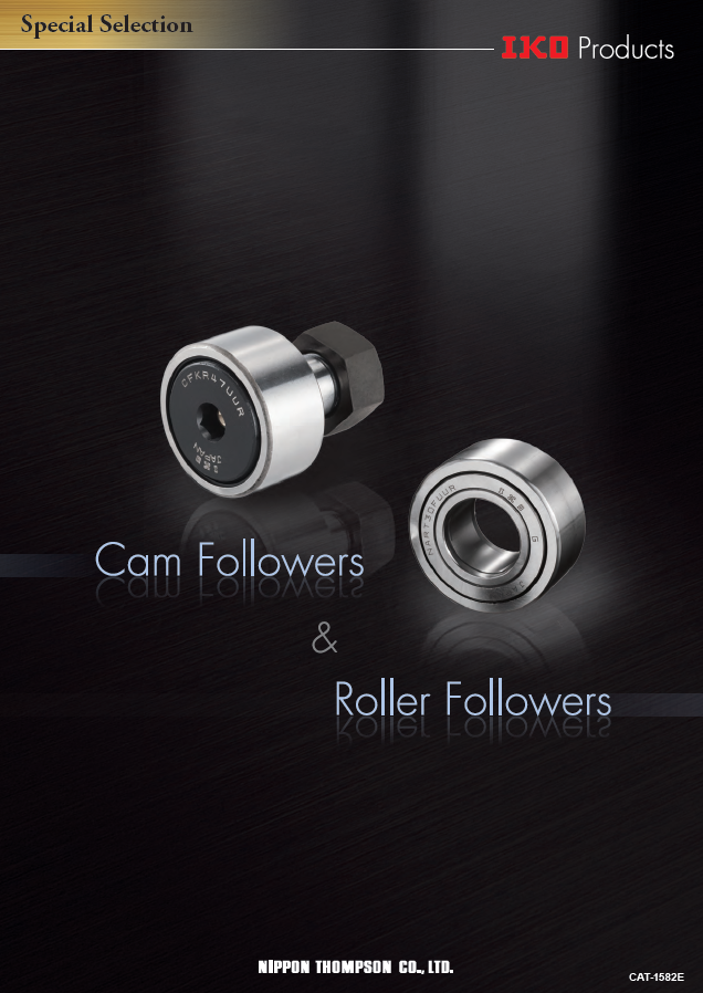
Cam Followers & Roller Followers
Cam Followers & Roller Followers
Page2
ExEpxeprtesr tisn iNn eNeedeled lRe oRlloelrl eBr eBaerianrginsg. s.
IKOIK OC aCma mFo Fllolwloewrse r&s R& oRlloelrl eFro Fllolwloewrsers
Cam FCoallmow Feorsllo awnedr sR oalnledr RFolleorw Feorsllo awree rcso amrep rcisoemdp orifs neede odfl en eroeldlelers r soullerrrosu snudrerodu bnyd ead t hbicy ka otuhticekr roinugte. r ring.
TheseT bheeasrein bgesa arrineg dse asrige ndeeds ifgonr erodt faotiro rno toaft itohne ofu ttheer roinugte, rw ritnhg a, wloitwh cao loefwfi ccioenetffi ocfi efrnict toiof nfr iacntido ne xacnedll enxtc reollteantito rno tation
performpearnfocrem. ance.
TheseT bheeasrein bgesa arrineg dse asrige ndeeds iwgnitehd a wsmitha lal rsamdaiall rcaledaiaral cnlceea rsaon acse tsoo eafsfe tcot ievfefleyc etixvpealyn edx tphaen ldo athdein lgo azdonineg. zone.
This enTshuisr eesn stuarbesle s atanbdl elo anngd l ifloen bgy lilfees sbeyn liensgs ethnein sgh tohcek slohoadck a lso athde a osu ttheer roinugte ro rlilnsg o rvoelrls t hoev emr athtien gm caatimng s ucarfmac seu. rface. Cam Follower Series
General Explanation ・・・・・・・・・・・・・・・・・・・・・・・・・5
A wideA v waridieet yv aorfi emtyo doef lms oardee alsv arilea balvea inla bolet hin C baomth F Coallmow Feorsllo wwitehr ss twuidths satnudd sR oalnledr RFolleorw Feorsllo wwitehr sin wniethr riinngesr. rings. Dimension Table ・・・・・・・・・・・・・・・・・・・・・・・・・・・31
Introduction of Customized Products ・・・・・・・・・119
Thus, Tanh uasp, parno parpiaptreo pbreiatrein bge caarinn gb ec asne lebcet esedl efocrt evda rfioru vsa oripoeursa toinpge rcaotindgi tci onsd. it ions. Model Comparison Table for Cam Followers ・・・121
They aTrhee oyf taerne uosfteedn fuosr ecda mfo rm ceacmh amneiscmhsa noirs mlinse oar lminoetaior nm onti ocno novne cyionngv eqyiunigp meqeunitp. ment.
External Lubrication Parts
for Cam Followers C-Lube Units
General Explanation ・・・・・・・・・・・・・・・・・・・・・・・・17
Dimension Table ・・・・・・・・・・・・・・・・・・・・・・・・・・・20
Roller Follower Series
General Explanation ・・・・・・・・・・・・・・・・・・・・・・・・81
Dimension Table ・・・・・・・・・・・・・・・・・・・・・・・・・・・89
Model Comparison Table for Roller Followers ・・・122
1 2
Page3
Table of contents、Cam Follower Series
CONTENTS CAM FOLLOWERS
Cam Follower Series CAM FOLLOWER Series
Explanation
Features ……………………………………………………………… 5 Allowable Rotational Speed ……………………… 25
C-Lube Unit for Cam Followers ………………… 19 Lubrication ……………………………………………………… 25
Identification Number …………………………………… 21 Oil Hole …………………………………………………………… 26
Load Rating and Life …………………………………… 22 Accessories …………………………………………………… 27
Maximum Allowable Static Load ……………… 22 Special Specification …………………………………… 28
Accuracy ………………………………………………………… 23 Operating Temperature Range ………………… 28
Radial Internal Clearance …………………………… 24 Mounting ………………………………………………………… 29
Fit ……………………………………………………………………… 24 Precautions for Use ……………………………………… 30
Track Capacity ……………………………………………… 25
Dimension Table
Miniature Type Cam Followers …………………………………… CFS …………………………………………………………………… 31
Thrust Disk Type Miniature Cam Followers ……………… CFS…W …………………………………………………………… 33
Standard Type Cam Followers CF…B ……………………… CF…B ……………………………………………………………… 35
Cam Follower G ……………………………………………………………… CF…G ……………………………………………………………… 39
Thrust Disk Type Cam Followers ………………………………… CF…WB …………………………………………………………… 41
C-Lube Cam Followers…………………………………………………… CF…WB…/SG ………………………………………………… 43
Solid Eccentric Stud Type Cam Followers ……………… CFES…B ………………………………………………………… 45
Eccentric Type Cam Followers …………………………………… CFE…B …………………………………………………………… 47
Standard Type Cam Followers CFKR ………………………… CFKR ………………………………………………………………… 51
Eccentric Type Cam Followers CFKRE ……………………… CFKRE ……………………………………………………………… 55
Centralized Lubrication Type Cam Followers ………… CF-RU1, CF-FU1 ………………………………………… 59
Easy Mounting Type Cam Followers ………………………… CF-SFU…B ……………………………………………………… 61
Cylindrical Roller Cam Followers ………………………………… NUCF…B ………………………………………………………… 63
Inch Series Cam Followers CR …………………………………… CR…B, CR ……………………………………………………… 65
Inch Series Cam Followers CRH ………………………………… CRH…VB ………………………………………………………… 73
Option Parts
Way for Cam Follower ………………………………… 75 Cam Follower Series
Roller Follower Series ROLLER FOLLOWER Series
Explanation Explanation Dimension Table
Features …………………………………………………………… 81 Track Capacity ……………………………………………… 87 Features ……………………………………………………………… 5 Miniature Type Cam Followers ………………………31
Identification Number …………………………………… 83 Allowable Rotational Speed ……………………… 87 C-Lube Unit for Cam Followers ……………………19 Thrust Disk Type Miniature Cam Followers ……33
Load Rating and Life …………………………………… 84 Lubrication ……………………………………………………… 87 Identification Number ………………………………………21 Standard Type Cam Followers CF…B …………35
Maximum Allowable Static Load ……………… 84 Oil Hole …………………………………………………………… 87 Load Rating and Life ………………………………………22 Cam Follower G ………………………………………………39
Accuracy ………………………………………………………… 85 Operating Temperature Range ………………… 87
Maximum Allowable Static Load …………………22 Thrust Disk Type Cam Followers …………………41
Radial Internal Clearance …………………………… 86 Mounting ………………………………………………………… 88
Fit ……………………………………………………………………… 87 Accuracy ……………………………………………………………23 C-Lube Cam Followers ……………………………………43
Dimension Table Radial Internal Clearance ………………………………24 Solid Eccentric Stud Type Cam Followers ……45
Separable Roller Followers …………………………………………… RNAST, NAST ………………………………………………… 89 Fit …………………………………………………………………………24 Eccentric Type Cam Followers ………………………47
Non-separable Roller Followers ………………………………… NART ………………………………………………………………… 93 Track Capacity …………………………………………………25 Standard Type Cam Followers CFKR …………51
C-Lube Roller Followers ………………………………………………… NART…/SG …………………………………………………… 97 Allowable Rotational Speed ……………………………25 Eccentric Type Cam Followers CFKRE ………55
Cylindrical Roller Followers …………………………………………… NURT ………………………………………………………………… 99 Lubrication …………………………………………………………25 Centralized Lubrication Type Cam Followers ……59
Inch Series Non-separable Roller Followers …………… CRY ………………………………………………………………… 101 Oil Hole ………………………………………………………………26 Easy Mounting Type Cam Followers ……………61
Accessories ………………………………………………………
Customized Products / Model Comparison Table / Miscellaneous Tables 27 Cylindrical Roller Cam Followers …………………63
Special Specification ………………………………………28 Inch Series Cam Followers CR ……………………65
Introduction of Customized Products …… 119 Model Comparison Table for Roller Followers … 122 Operating Temperature Range ………………………28 Inch Series Cam Followers CRH …………………73
Model Comparison Table for Cam Follower s… 121 Miscellaneous Tables ………………………………… 123 Mounting ……………………………………………………………29
Option Parts
Precautions for Use …………………………………………30
Introduction of Technical Service Site 131 Way for Cam Follower ……………………………………75
3 4
Cam Followers
Page4
Explanation
CAM FOLLOWERS
Cam Followers
IKO Cam Followers are bearings incorporating needle rollers with a stud enclosed in a thick
CF Variety & Originality
outer ring. These bearings are designed for outer ring rotation with superior rotational
performance, a low coefficient of friction and high load capacity. Cam Followers have a
high rigidity and accuracy making them well suited for various applications such as cam
mechanisms and guide rollers for linear motion. They have a wide range of uses such as Reliable and Proven Cam Follower Series!
machine tools, industrial robots, electronic parts and office automation equipment.
The hexagon socket on the stud head allows for secure tightening with a hexagon wrench
as means for mounting. In addition, IKO’s original lubrication structure enables the Cam
Follower to be lubricated from multiple locations including the stud head allowing for more
freedom when designing equipment.
Introducing the features of Cam Follower excellence!
Cage
Outer Ring Well suited for high speed due to its excellent
Thick structure helps rotational properties.
resist shock loads. ❶ Substantial Product Lineup
Stud 7
Machined Our substantial product lineup offers types such as extremely-small-sized page
threads make miniature, built-in thrust disk good for mounting errors, maintenance free
for easy with pre-packed solid lubricant as well as other types.
mounting.
Grease Nipple
Enables lubrication
via grease gun as Side plate ❷ Wide Selection of Product Specifications
well as functions as Quench-hardened for
a plug. increased wear resistance. to match your needs
14
Seal Options such as material type, roller guide method, seal structure page
Totally sealed to prevent and shape of the outer ring surface are available to meet the needs
foreign substances of your application.
entering the bearing.
Hexagon Socket Needle Roller
Hexagon wrench can
The use of crowning rollers helps
be used to secure. ❸ Hexagon Socket for Easy Mounting
prevent misalignment. 15
The hexagon socket on the stud head allows for easy means of page
Standard Type Cam Followers mounting with hexagon wrench.
❹ Original Lubricating Structure
which allows for lubrication from the stud head
16
The hexagon socket’s unique design allows for grease to be page
administered from the stud head end.
❺ New Innovation of C-Lube Unit for Cam Followers
17
The C-Lube unit supplies lubrication oil to the outside surface of page
the Cam Follower’s outer ring and the track surface. Thus reducing
friction and wear as well as eliminating the need to routinely grease
these surfaces.
Miniature Type Cam Followers
5 6
Cam Followers
Page5
CAM FOLLOWERS
❶ Substantial product lineup 1
Miniature Type Cam Followers Stud diameter mm Standard Type Cam Followers (Stud Head Hex Hole) Stud diameter mm
2 to 6 3 to 30
CFS Selectable product specifications CF…B Selectable product specifications
No High carbon No High carbon
Type of symbol steel Type of symbol steel
material
Ultrafine needle roller is incorporated to the outer ring of bearing so the compact F Stainless material F Stainless
steel These are the basic bearing models in the Cam Follower series. Size variations steel
design is realized with outer ring outside diameter which is small relative to the No
Roller guide symbol With cage from 3 to 30 mm in stud diameter are available. No
Roller guide symbol With cage
stud diameter. They are used in electronic devices, OA equipment, small index method V Full method V Full
devices, etc. complement complement
No No
Seal symbol Shield type Seal symbol Shield type
Cage structure UU Sealed type structure UU Sealed type
Stud Stud
Shape of No Cylindrical Shape of No Cylindrical
outer ring
outer ring symbol symbol outer ring
Crowned outer ring Crowned
outside surface R outer ring outside surface R outer ring
Side plate Side plate Cam Follower G
Needle roller Needle roller Seal Cage Selectable product specifications
CFS Outer ring CFS…V Outer ring Outer ring Side plate CF…G No High carbon
Type of symbol steel
material
F Stainless
steel
No
Cam Followers with Roller guide symbol With cage
method Full
pre-packed grease at V complement
No
reasonable price. Seal symbol Shield type
Stud structure UU Sealed type
Needle
No Cylindrical
roller Can be used as-is when opened Shape of
symbol outer ring
31 35 Pre-packed grease outer ring
R Crowned
outside surface
page page outer ring
Thrust Disk Type Miniature Cam Followers Stud diameter mm Thrust Disk Type Cam Followers Stud diameter mm
1.4 to 6 3 to 20
CFS…W Selectable product specifications
No High carbon CF…WB Selectable product specifications
No High carbon
Type of symbol steel Type of symbol steel
material
F Stainless material F Stainless
Miniature Type Cam Followers incorporated with special synthetic resin thrust steel As it is incorporated with special synthetic resin thrust washers excellent in wear steel
washers excellent in wear and heat resistance. It receives axial load of outer ring No
Roller guide symbol With cage and heat resistance, it receives axial load of outer ring generated due to mounting No
Roller guide symbol With cage
generated due to installation errors to prevent friction and wear on the sliding surface. method Full errors to prevent friction and wear on the sliding surface. method Full
V complement Thrust Disk V complement
No Thrust Disk No
World's smallest size! Seal symbol Shield type Seal symbol Shield type
structure UU Sealed type structure UU Sealed type
A Cam Follower with Shape of No Cylindrical Shape of No Cylindrical
stud diameter of just 1.4 mm!! symbol outer ring symbol outer ring
outer ring Crowned outer ring Crowned
outside surface R outer ring outside surface R outer ring
Ultra-compact CFS1.4WV with a stud diameter of 1.4 mm and
outer ring diameter of just 4 mm. The built-in thrust disk
receives the axial load of the outer ring generated due to
mounting errors. 41
page
5 Features of CFS1.4WV
1 Stud diameter 2 Outside dia. 3 Hexagon socket 4 Full complement type 5 Includes thrust disks
Just of outer ring for easy mounting for large load capacity to resist mounting errors
φ1.4 mm Just φ4 mm
33
page
7 1N=0.102kgf=0.2248lbs.
1mm=0.03937inch 8
Cam Followers
Page6
CAM FOLLOWERS
❶ Substantial product lineup 2
C-Lube Cam Followers Stud diameter mm Solid Eccentric Stud Type Cam Followers Stud diameter mm
5 to 20 6 to 18
CF···WB···/SG Selectable product speci cations CFES…B Selectable product specifications
No High carbon No High carbon
Type of symbol steel Type of symbol steel
material
F Stainless material
Rotation of eccentric stud can align height of outer ring outside diameter when F Stainless
Maintenance free product with thermoset solid lubricant C-Lube pre-packed in the bearing space. steel steel
No No
C-Lube is heat-treated and solidi ed lubricant composed of an amount of lubrication oil and particulate Roller guide symbol With cage multiple rings are used. Eccentricity is from 0.25 to 0.6 mm and it can be mounted Roller guide symbol With cage
ultra-high molecular polyethylene resin. As the bearing rotates, the lubricant oozes out of C-Lube onto method Full to the same mounting hole as the Standard Type Cam Followers. method Full
V complement V complement
the raceway in proper quantities, maintaining the lubrication performance for a long period of time. No No
Seal symbol Shield type Seal symbol Shield type
structure UU Sealed type structure UU Sealed type
Thrust Disk Shape of No Cylindrical Shape of No Cylindrical
symbol
outer ring outer ring symbol outer ring
Crowned outer ring Crowned
outside surface R outer ring outside surface R outer ring
C-Lube
Eccentric stud
Maintenance-free 45
page
and Eco-friendly
Eccentric Type Cam Followers (Stud Head Hex Hole) Eccentric collar diameter mm
9 to 41
<Lubrication performance test> CFE…B Selectable product specifications
No High carbon
Test conditions Test Result Type of symbol steel
100 material F Stainless
Test portion CF10WBUUR/SG In these bearings, an eccentric collar is assembled with the Cam Follower stud, steel
Lubrication conditions C-Lube only, no pre-packed grease C-Lube Cam Followers
enabling the outer ring to be positioned easily in the radial direction against the mating No
75 Roller guide
Rotational speed 1000 min-1 symbol With cage
cam guide surface by rotating the stud. Eccentricity is from 0.4 to 1.5 mm. method Full
Ambient temperature Room temperature V complement
50 No
Seal symbol Shield type
structure
25 UU Sealed type
Shape of No Cylindrical
0 symbol
outer ring outer ring
0 1 000 2 000 3 000 4 000 5 000 43 Crowned
Operating time min outside surface R
page outer ring
Ideal for combination with C-Lube Units for Cam Followers!!
The combination with C-Lube Unit for Cam
Follower realizes maintenance-free of Cam Follower
inside and cam guide surface.
Eccentric collar
17
page 47
page
9 1N=0.102kgf=0.2248lbs.
1mm=0.03937inch 10
Lubrication oil residue %
Eccentricity ε Eccentricity ε
(0.4 to 1.5 mm) (0.25 to 0.6 mm)
Cam Followers
Page7
CAM FOLLOWERS
❶ Substantial product lineup 3
Standard Type Cam Followers (Double Hex Hole) Stud diameter mm Centralized Lubrication Type Cam Followers Stud diameter mm
10 to 30 6 to 30
CFKR Selectable product specifications CF-RU1, CF-FU1 Selectable product specifications
No High carbon No High carbon
Type of symbol steel Type of symbol steel
material F Stainless material
As a tapped hole is prepared for the centralized piping on the stud head, this is F Stainless
CFKR have a structure with hexagon sockets at each end of the stud and can be steel steel
mounted using a hexagon wrench as baffle from either end, leaving the mounting No
Roller guide symbol With cage optimal for applications where centralized oil piping is necessary. No
Roller guide symbol With cage
location unrestricted. method V Full method V Full
complement complement
No
Seal symbol Shield type No
Seal symbol Shield type
structure UU Sealed type structure No
symbol Sealed type
Shape of No Cylindrical Shape of FU1 Cylindrical
symbol outer ring
outer ring outer ring
outer ring Crowned Crowned
outside surface R outer ring outside surface RU1 outer ring
Hexagon socket
Tapped hole for
Centralized Lubrication
When the stud thread is interfering When the stud head is interfering 51 59
page page
Eccentric Type Cam Followers (Double Hex Hole) Eccentric collar diameter mm Easy Mounting Type Cam Followers Stud diameter mm
13 to 35 6 to 20
CFKRE Selectable product specifications CF-SFU…B Selectable product specifications
No High carbon No High carbon
Type of symbol steel Type of symbol steel
material F Stainless material F Stainless
An eccentric collar is assembled with the Double Hex Hole CFKR, and is enabling steel These bearings have a stepped tapered portion on the stud, making mounting easy steel
the outer ring to be positioned easily in the radial direction against the mating cam No
Roller guide symbol With cage by fixing a set screw to the stepped portion: thus they are optimal for applications No
Roller guide symbol With cage
guide surface by rotating the stud. Eccentricity is from 0.5 to 1.5 mm. method Full such as pallet change.
V method V Full
complement complement
No
Seal symbol Shield type No
Seal symbol Shield type
structure UU Sealed type structure No
symbol Sealed type
Shape of No Cylindrical Shape of No Cylindrical
symbol outer ring
outer ring symbol outer ring
Eccentric collar Crowned outer ring Crowned
outside surface R outer ring outside surface R outer ring
Eccentric collar
Eccentric collar Mounting hole
Stud Outer ring
Stepped taper
Contact surface
Rotate the stud to adjust the height. 55 CRH···B 61
page page
11 1N=0.102kgf=0.2248lbs.
1mm=0.03937inch 12
Eccentricity ε
(0.5 to 1.5mm)
Cam Followers
Page8
Cam Follower product series
CAM FOLLOWERS
❶ Substantial product lineup 4 ❷ Wide selection of product specifications for your use
Type of material <High carbon steel made> <Stainless steel made>
Cylindrical Roller Cam Followers Stud diameter mm
10 In addition to high carbon steel products, stainless
to 30 steel products are also available. Stainless steel
products are suited for applications where oil
NUCF…B Selectable product specifications should be avoided, water is spattering, or it is For sections
No High carbon used in a clean room. where oil should be avoided
Type of symbol steel
material
F Stainless For general use... and environment
These bearings incorporate double rows of full complement cylindrical rollers in the steel where water is spattering...
outer ring, and are able to withstand large radial loads. Additionally, the outer ring is No
Roller guide symbol With cage
guided by the outer ring shoulder and the end face of cylindrical rollers to the axial method No Full
direction. symbol complement Roller guide method
No For sections with high-speed rotation... For sections with low-speed rotation or heavy load...
Seal symbol Shield type
structure As caged type has smaller friction coefficient, it is suited for
UU Sealed type high-speed rotation.
Shape of No Cylindrical Full complement type is suited for sections where low-speed
outer ring
outer ring symbol rotation, oscillatory movement or heavy load exists.
Crowned
outside surface R outer ring
<With cage> <Full complement>
Allowable rotational speed comparison Dynamic load rating comparison
30 000 80 000
Caged type oil lubrication With cage
70 000
25 000 Full complement oil lubrication Full complement
Caged type grease lubrication 60 000
20 000
Full complement grease lubrication 50 000
15 000 40 000
30 000
10 000
Cylindrical roller 20 000
63 5 000
10 000
page
0 0
5 6 8 10 12 16 18 20 24 30 5 6 8 10 12 16 18 20 24 30
Stud diameter mm Stud diameter mm
Inch Series Cam Followers Stud diameter mm
Seal structure
4.826 to 50.800 For dust prevention
For general use...
Shield type is shaped so that clearance between the outer ring and grease leak prevention...
CR…B, CRH…B Selectable product specifications and stud flange and between the outer ring and side plate
No High carbon become smaller and labyrinth is formed.
Type of symbol steel The sealed type has an incorporated seal ideally shaped to
material
F Stainless
2 types of Inch Series Cam Followers are available: CR and CRH. CRH has large steel prevent the penetration of foreign substances.
load rating and is a heavy duty type with black oxide film treatment. No
Roller guide symbol With cage
method Full
V complement <Shield type> <Sealed type>
No
Seal symbol Shield type
structure UU Sealed type
Shape of No Cylindrical Shape of outer ring outside surface For reducing For sections with high applied load...
symbol outer ring
outer ring For cam guide surfaces without
Crowned Crowned outer ring is effective for mitigation of edge load mounting errors...
outside surface R enough hardness...
outer ring generated due to mounting errors.
Cylindrical outer ring is suited if the applied load is large or
hardness of cam guide surface is low.
Track capacity comparison *Value when the mating member material hardness is 40HRC.
70 000
Crowned outer ring
60 000 Cylindrical outer ring <Crowned outer ring> <Cylindrical outer ring>
50 000
40 000
30 000
20 000
CRH···B 65 10 000
page 0
13 16 19 22 26 30 32 35 40 52 47 62 72 80 85 90
13 Outside diameter of outer ring mm 1N=0.102kgf=0.2248lbs.
1mm=0.03937inch 14
Load capacity N Number of revolutions min-1
Basic dynamic load rating C N
R
Cam Followers
Page9
CAM FOLLOWERS
❸ Hexagon Socket for easy mounting ❹ Original Lubricating Structure which allows for lubrication from the stud head
Easily secure stud Original lubricating structure
with the help of a hexagon wrench! Hex Head Cam Followers allow lubrication from the stud head.(1)
Hex Head Cam Followers 3 Way 3 Way Type
Stud dia. 12 to 30 mm (2)
Embedded into the stud end surfaces so
the outside dimensions aren't changed. (3) Innovative design where the stud end
Hexagon
Hexagon nipple doesn't protrude.
Socket
wrench
Hexagon socket is available in the following series Attached grease nipple
Series name Model Stud diameter (mm)(1)
Miniature Type Cam Followers CFS 2 to 6 Grease nipple
built in the
Thrust Disk Type Miniature Cam Followers CFS…W 1.4 to 6 hexagon socket!!
Lubrication from any one of
3 angles with the outside
dimensions unmodified!!
Standard Type Cam Followers (Stud Head Hex Hole) CF…B 3 to 30
Thrust Disk Type Cam Followers CF…WB 3 to 20
C-Lube Cam Followers CF…WB…/SG 5 to 20
Solid Eccentric Stud Type Cam Followers CFES…B 6 to 18 Conventional Type
Eccentric Type Cam Followers (Stud Head Hex Hole) CFE…B 9 to 41 1 Way 1 Way Type
Standard Type Cam Followers (Double Hex Hole) CFKR 10 to 30 Furthermore, there is no need to differentiate
(4Eccentric Type Cam Followers (Double Hex Hole) CFKRE 13 to 35 )
Stud dia. 5 to 10 mm between the use of a plug or a grease nipple
Easy Mounting Type Cam Followers CF-SFU…B 6 to 20 depending on the lubrication direction.
Cylindrical Roller Cam Followers NUCF…B 10 to 30
Inch Series Cam Followers CR…B, CRH…B 4.826 to 50.800
* Centralized Lubrication Type Cam Followers come with a screwdriver slot.
Note (1) It shows the eccentric collar diameter for Eccentric Type Cam Followers.
CFKR(E) is designed with hexagon sockets at each end of the stud,
allowing for use in any mounting location!
Grease can be fed
Hexagon
Socket Drastically improved
mounting options!! from the stud head!
Numerous lubrication ports permits
multiple lubrication methods!!
Notes (1) Excluding Miniature Type Cam Followers, Thrust Disk Type
Miniature Cam Followers, Standard Type Cam Followers CF···B
with 3 mm or 4 mm stud diameters, Cam Follower G, C-Lube
Cam Followers and Inch Series Cam Followers.
(2) Eccentric Type Cam Followers have a stud thread diameter G
as shown in the dimension table.
Furthermore, all Easy Mounting Type have a 1way port.
(3) Grease nipple for stud end is included as an accessory.
(4) Oil holes are provided on both stud ends for CFKR(E) only.
(2 Way Type) For CFKR(E), a grease nipple is incorporated in
When the stud thread end When the stud head end the stud head.
is obstructed is obstructed
15 1N=0.102kgf=0.2248lbs.
1mm=0.03937inch 16
Cam Followers
Page10
CAM FOLLOWERS
❺ New Innovation of C-Lube Unit for Cam Followers
C-Lube Unit for Cam Followers CL C-Lube Unit For Cam Follower CL Applications
Achieves long term maintenance free cam guide surfaces!!
IKO C-Lube Unit for Cam Followers is a lubrication component that Conventional Cam Followers Lubrication maintenance
mounts on Cam Followers. Frequent lubrication is not required not required over long term use!!
since oil is administered to the outer ring and track surfaces. 19
page
Long-term operation without the need for costly frequent lubrication!
Mounting dimensions,
structure as-is (1) When combined with CL
Capillary lubricating element
C-Lube Unit 1
Constructed by sintering a fine Notes ( ) Cam Followers only need to be offset by a few mm in the axial directions to cater for the CL resin cover thickness.
resin powder into a porous
mold. The porous mold is then
saturated with a large amount CL properties are underpinned by extensive durability testing!
of lubrication oil.
Before impregnating oil <Durability test>
Test conditions (2) Test Result
100
Test portion CL12 C-Lube Unit For Cam Followers Sample 1
CF12 WBUUR/SG C-Lube Cam Followers 95
Lubrication conditions C-Lube Unit only, no pre-packed grease
Fusion-bonded 90
Maximum speed 2000 mm/s Sample 2
Resin particles are firmly fused Stroke length 300 mm 85
together with numerous empty Track surface Material SKD11
spaces. 80
specifications Hardness 58HRC or more
Surface Roughness Rz: 6.3 μm or less 75
After impregnating oil Ambient temperature Room temperature
70
Notes (2) Uses a ground cam guide surface with verified durability. 0 10 000 20 000 30 000
If using under different conditions, please confirm with Traveling distance km
your actual machine.
C-Lube Cam Followers C-Lube Unit
Resin part Lubricant part For Cam Followers C-Lube Cam Followers
Note Please purchase as a separate
addition to the IKO C-Lube Unit. Lubricant is retained in cavities
amongst resin particles.
Cam guide surface
Are you struggling C-Lube Unit CL
with problems like this? If so, problem solved!! Ideal for use in combination with C-Lube Cam Followers!!
When lubrication maintenance of cam guide surfaces is not right... The combination of IKO Cam Followers CF…WB…/SG with the IKO C-Lube Unit for Cam
d Completely
Lubrication oil runs low allowing Too much grease causes it y applie Followers provides for maintenance-free operation both inside and outside the Cam
wear and reddish-brown rust to to scatter, thus contaminating tinuousl Follower as well as the track surface. maintenance free!
appear! the surrounding environment! l is con
f time!
Filled with a solid Cam Follower interior Cam guide surface
Lubrication oi
period o
type lubricant for
for a long
sustained lubrication
C-Lube Unit performance over long
CL periods of time!
C-Lube
Needle roller
C-Lube
IKO C-Lube Cam Followers IKO C-Lube Unit for Cam Followers
CL
nce of s o CF…WB…/SG
nation t
Occurre t
rown rus rounding nment!
contami
g enviro
Remark C-Lube Units can be used in combination with Standard Type Cam Followers, Cam Follower G, Thrust Disk Type Cam Followers, Centralized
reddish-b lthy sur
Lubrication Type Cam Followers, C-Lube Cam Followers and Cylindrical Roller Cam Followers.
17 due to wear! Fi
due to grease! Prevents
the surroundin
1N=0.102kgf=0.2248lbs.
1mm=0.03937inch 18
Lubrication oil residue %
Cam Followers
Page11
CAM FOLLOWERS
C-Lube Unit for Cam Followers
❶ Identification Number ❺ Mounting ❻ Precautions for Use ・ Before operation, ensure that lubrication oil is supplied
An example of the identification number of C-Lube Unit for ・ Set the C-Lube Unit perpendicularly to a center line of the ・ Never clean up a C-Lube Unit with organic solvent or white between the Cam Followers outer ring outside surface and
Cam Followers is shown below. Cam Follower stud and fix it along with the Cam Follower kerosene with property of removing fat. the cam guide surface. Lubrication performance of the
with a nut. (See Fig. 1) ・ To avoid damage and lubrication function failure, do not C-Lube Unit is largely affected by conditions of the cam
directly apply load onto the C-Lube Unit. guide surface.
・ To rotate the Cam Followers normally with the C-Lube Unit ・ Avoid operating the C-Lube Unit in any environment where
CL 12-1 mounted, apply load of 1% or more of the basic dynamic capillary lubricating elements may be damaged or foreign
load rating to the Cam Followers. substances or liquid substance may enter into it.
・ Load applied to the Cam Follower with the C-Lube Unit ・ As additional oil feeding to the C-Lube Unit is not allowed,
Model code equipped must be 80% or less of the maximum allowable replace it with new one when lubrication effect is lost.
static load of the Cam Follower to be combined. Excessive
Dimensions load may deform the C-Lube Unit mounting surface,
Indicates the stud diameter of Cam Followers. loosen the Cam Follower fixed nut, or dislodge the C-Lube
(unit: mm) Unit, preventing normal operation.
Fig. 1 Mounting C-Lube Units
❼ Dimension Table
❷ Allowable Rotational Speed ・ C-Lube Unit must be positioned avoiding loading direction.
For Cam Followers with C-Lube Unit mounted, use 10,000 In addition, the C-Lube Unit has no baffle, so fix it while
W T
or lower as reference for the d1n value. adjusting the C-Lube Unit position in mounting. (See Fig. 2)
d1n value = d1 x n
where d1 : Stud diameter of Cam Follower mm
n : Rotational speed min-1
❸ Minimum Rotational Angle φD
Lubrication oil is supplied to the whole outside diameter
surface of the outer ring. Accordingly, when the C-Lube
Unit is mounted, use the product in conditions under Load B t1
which the outer ring makes one or more turns. Fig. 2 Loading Direction of Cam Followers
Boundary dimensions mm Applicable Cam Followers
❹ Operating Temperature Range
Identification number Boundary dimensions mm
Use the C-Lube Unit within the temperature range between ・ Tighten the nut to fix the C-Lube Unit and Cam Followers W H T t1 Identification number(1)
-15°C and 80°C. together to the extent not exceeding the maximum D B
tightening torque specified in the Cam Followers dimension CL 5 12.4 10.7 12.1 1.5 CF 5 B 13 10
table. CL 6 15.4 12.6 14 1.5 CF 6 B 16 12.2 max
・ In case loosening of the nut is predicted due to vibration, CL 8 18.4 14.2 14 1.5 CF 8 B 19 12.2 max
using lock nut, spring washer and other self-locking nut
CF 10 B
are recommended. CL 10 21 17 15.5 2 22 13.2 max
CFKR 22
CF 10-1 B
CL 10-1 21 19.2 15.5 2 26 13.2 max
CFKR 26
CF 12 B
CL 12 29 21 17.5 2 30 15.2 max
CFKR 30
CF 12-1 B
CL 12-1 29 22 17.5 2 32 15.2 max
CFKR 32
CF 16 B
CL 16 33.8 27.4 23.4 2.5 35 19.6 max
CFKR 35
CF 18 B
CL 18 38.8 30.4 25.4 2.5 40 21.6 max
CFKR 40
CF 20 B
CL 20 45.8 38.4 29.9 3 52 25.6 max
CFKR 52
CF 20-1 B
CL 20-1 45.8 35.4 29.9 3 47 25.6 max
CFKR 47
Note (1) Only representative identification numbers are shown here; however, this table is applicable to the same size of Standard Type Cam
Followers, Cam Follower G, Thrust Disk Type Cam Followers, Centralized Lubrication Type Cam Followers, C-Lube Cam Followers
and Cylindrical Roller Cam Followers.
Use in combination with C-Lube Cam Followers is strongly recommended for full maintenance free effect.
Remark Load applied to the Cam Follower with the C-Lube Unit equipped must be 80% or less of the maximum allowable static load of the
Cam Follower to be combined. For the maximum allowable static load of each Cam Follower, please see the dimension tables of
respective models.
19 1N=0.102kgf=0.2248lbs.
1mm=0.03937inch 20
H
Cam Followers
Page12
CAM FOLLOWERS
Identification Number Load Rating and Life
Examples of the identification number of Cam Followers are shown below. In addition, for application of material type, roller Basic dynamic load rating C Load factor
guide method, seal structure and shape of outer ring outside surface to each model, refer to the dimension table.
Basic dynamic load rating refers to a static radial load with a Load actually applied on the Cam Followers becomes larger
Example of Identification Number certain direction and size with which 90% of a group of the than load theoretically calculated from vibration and shock.
same Cam Followers can run one million rotations without Therefore, multiply the load by the load factor shown in
Example 1 CFS 3 F V P6 material damages due to rolling contact fatigue when they Table 2.
are operated in the same conditions.
Example 2 CF 10 V B UU R
Basic static load rating C Table 2 Load factor
0
Example 3 CF 5 F W B UU R Operating conditions fw
Basic static load rating refers to a static radial load with a Smooth operation free from shock 1 to 1.2
certain direction and size with a certain contact stress at the
Example 4 CF 8 W B UU R /SG Normal operation 1.2 to 1.5
center of contact parts of the rolling elements and a raceway
under maximum load. Operation with shock load 1.5 to 3
Model code
Life
CFS Miniature Type Cam Followers
CFS…W Thrust Disk Type Miniature Cam Followers
Standard Type Cam Followers (Double Hex Hole) The basic rating life calculation formulas are shown below.
CF…B
CF…G Cam Follower G L10 = (CP )10/3 (1) Maximum Allowable Static Load
CF…WB Thrust Disk Type Cam Followers r
CF…WB…/SG C-Lube Cam Followers Where, L10 : Basic rating life 106 rev. The applicable load on Cam Followers is, in some cases,
CFES…B Solid Eccentric Stud Type Cam Followers C : Basic dynamic load rating N limited by the bending strength and shear strength of the
CFE…B Eccentric Type Cam Followers (Stud Head Hex Hole)
CFKR Standard Type Cam Followers (Double Hex Hole) Pr : Dynamic equivalent radial load N stud and the strength of the outer ring instead of the load
CFKRE Eccentric Type Cam Followers (Double Hex Hole) Therefore, life time can be calculated by applying the rating of the needle roller bearing. Therefore, the maximum
CF-RU1 Centralized Lubrication Type Cam Follower (Crowned Outer Ring) rotational speed to the formula below. allowable static load that is limited by these strengths is
CF-FU1 Centralized Lubrication Type Cam Follower (Cylindrical Outer Ring) specified.
CF-SFU…B Easy Mounting Type Cam Followers Lh = 106L10
60n (2)
NUCF…B Cylindrical Roller Cam Followers
CR…B Inch Series Cam Followers (Stud Head Hex Hole) Where, Lh : Basic rating life represented by service
CR Inch Series Cam Followers (With Screwdriver Slot) hours h
CRH…B Inch Series Cam Followers (Stud Head Hex Hole) n : Rotational speed min-1
Dimensions Static Safety Factor
The value indicates the stud diameter. (unit: mm)
(CFKR and CFKRE show the outer ring outside diameter dimensions.) Static safety factor can be obtained by the following equation
For Inch Series Cam Followers, outer ring outside and typical values are shown in Table 1.
diameter dimensions are indicated in 1/16 inch. C
fs =
0
P (3)
0r
Type of material Where, fs : Static safety factor
No symbol High carbon steel made C0 : Basic static load rating N
F Stainless steel made P0r : Static equivalent radial load (maximum
load) N
Roller guide method (1)
No symbol With cage
V Full complement Table 1 Static safety factor
Note (1) Cylindrical Roller Cam Followers are full complement type with no symbol. Operating conditions of the bearing fs
Seal structure (1) When high rotational accuracy is required ≥3
No symbol Shield type For ordinary operation conditions ≥1.5
UU Sealed type For normal operating conditions not
Note (1) Centralized Lubrication Type and Easy Mounting Type Cam Followers are sealed type with no symbol. requiring very smooth rotation ≥1
When it is rarely rotated
Shape of outer ring outside surface
No symbol Cylindrical outer ring
R Crowned outer ring
Accuracy class
No symbol Accuracy class 0
P6 Accuracy class 6 Applicable to Miniature
P5 Accuracy class 5 Type Cam Followers CFS
P4 Accuracy class 4 and CFS…W.
21 1N=0.102kgf=0.2248lbs.
1mm=0.03937inch 22
Cam Followers
Page13
CAM FOLLOWERS
Accuracy Radial Internal Clearance
The accuracy of Cam Followers is shown in Table 3, Table 4.1, Table 4.2, and Table 4.3. Radial internal clearance of Cam Followers is shown in Table 5.
We also provide special accuracy class products. For details, please contact IKO.
Table 5 Radial internal clearance unit: μm
Table 3 Tolerances unit: μm Identification number Radial internal clearance
Series Miniature Type Cam Followers Standard Type Cam Followers (1) Inch Series Cam Followers Miniature Type Cam Followers Standard Type Cylindrical Roller
Item CFS, CFS…W Crowned outer ring Cylindrical outer ring Crowned outer ring Cylindrical outer ring CFS, CFS…W Cam Followers (1
Inch Series Cam Followers Min. Max.
) Cam Followers
0 0 CFS1.4 to CFS5 CF 3B to CF 5 B - CR 8, CR 8-1, CRH 8-1, CRH 9 3 17
Outside dia. of outer ring D See Table 4.1 - See Table 4.2 e Table 4.3
50 - S e
50 CFS6 CF 6B - CR10, CR10-1, CRH10-1, CRH11 5 20
+
Stud diameter d1 h6 25
h7 - CF 8 to CF 12-1
0 - CR12 to CR22, CRH12 to CRH22 5 25
CFKR(E)22 to CFKR(E)32
0 0 0
Width of outer ring C - CF 16 to CF 20-1
-120 -120 -130 - CR24 to CR36, CRH24 to CRH36 10 30
CFKR(E)35 to CFKR(E)52
Note (1) Applicable for Cam Followers other than Miniature Type Cam Followers and Inch Series Cam Followers.
- CF 24 to CF 30-2 - CR48, CRH40 to CRH56 10 40
CFKR(E)62 to CFKR(E)90
Table 4.1 Tolerance and allowance of outer ring (Miniature Type Cam Followers CFS and CFS…W) unit: μm - - - CRH64 15 50
Δ - - NUCF10 B to NUCF24 B - 20 45
Dmp Kea
Deviation of mean outside diameter in a single plane Radial runout of outer ring of assembled bearing - - NUCF24-1B to NUCF30-2B - 25 50
(Maximum)
Note (1) Applicable for all Cam Followers other than Miniature Type Cam Followers, Cylindrical Roller Cam Followers and Inch Series Cam
Class 0 Class 6 Class 5 Class 4 Class 0 Class 6 Class 5 Class 4 Followers.
High Low High Low High Low High Low
0 -8 0 -7 0 -5 0 -4 15 8 5 4
Table 4.2 Tolerance and allowance of outer ring (Standard Type Cam Followers, Cylindrical outer ring) unit: μm Fit
D ΔDmp VDsp VDmp Kea
Nominal outside diameter of Deviation of mean outside Variation of outside Variation of mean Radial runout of outer ring Recommended fit of the Cam Followers stud and mounting hole is shown in Table 6 and dimensional tolerances of mounting
outer ring diameter in a single plane diameter in a single plane outside diameter of assembled bearing
mm (Maximum) (Maximum) (Maximum) hole are shown in Table 7, respectively. Since the Cam Follower is supported in a cantilever position, the mounting hole
diameter should be prepared without play between the stud and the hole especially when heavy shock loads are applied.
Over Incl. High Low
6 18 0 - 8 10 6 15
18 30 0 - 9 12 7 15 Table 6 Recommended fit
30 50 0 -11 14 8 20 Model of bearing Tolerance class of mounting hole for stud
50 80 0 -13 16 10 25 Miniature Type Cam Followers CFS, CFS…W H6
80 120 0 -15 19 11 35 Standard Type Cam Followers (1) H7
Inch Series Cam Followers F7
Note (1) Applicable for Cam Followers other than Miniature Type Cam Followers and Inch Series
Table 4.3 Tolerance and allowance of outer ring (Inch series Cam Followers, Cylindrical outer ring) unit: μm Cam Followers.
D ΔDmp VDsp VDmp Kea
Nominal outside diameter of Deviation of mean outside Variation of outside Variation of mean Radial runout of outer ring
outer ring diameter in a single plane diameter in a single plane outside diameter of assembled bearing
mm (Maximum) (Maximum) (Maximum) Table 7 Dimensional tolerances of mounting hole unit: μm
Over Incl. High Low Classification of diameter
F7 H6 H7
mm
6 18 10 6 15
Over Incl. High Low High Low High Low
18 30 12 7 15
- 3 +16 + 6 + 6 0 +10 0
30 50 0 -25 14 8 20
3 6 +22 +10 + 8 0 +12 0
50 80 16 10 25
6 10 +28 +13 + 9 0 +15 0
80 120 19 11 35
10 18 +34 +16 +11 0 +18 0
18 30 +41 +20 +13 0 +21 0
30 40 +50 +25 +16 0 +25 0
40 50
23 1N=0.102kgf=0.2248lbs.
1mm=0.03937inch 24
Cam Followers
Page14
CAM FOLLOWERS
Track Capacity Table 9 d1n values of Cam Followers
Lubrication Grease Oil Hole
Oil lubrication
Model of bearing lubrication
Track capacity is defined as the load which can be The position of oil hole is shown in Table 11. Table 12 Models and dimensions of supply nozzle
With cage 84 000 140 000
continuously applied on a Cam Follower placed on a steel Perform greasing quietly by fitting a lubrication nozzle shown in Table 12 to Applicable grease
cam guide surface without causing deformation or Full complement 42 000 70 000 a straight type grease gun in JIS B 9808 and pressing the nozzle against the Model Dimension nipple and
indentation on the cam guide surface when the outer ring of Cylindrical Roller Cam Followers 66 000 110 000 grease nipple or re-greasing fitting. re-greasing fitting
the Roller Follower makes contact with the mating cam guide When the NPT type grease nipple of the special specifications shown in Width
126 29 across
surface (plane). Track capacities shown in the dimension Table 19 and NPB type grease nipple shown in Table 15 are mounted, you NPF3 (1)
at 12
Width across ats 12 s
NPF4-1 (1)
table are values on the assumption that hardness of the may also fill grease by pressing the grease gun without using a supply A-5126T NPF6-1 (1)
mating member material is 40HRC (tensile strength: 1250 N/ Lubrication nozzle specified in Table 12. Re-greasing
mm2) and if hardness is not 40HRC, these values must be In addition, oil cannot be fed for those without oil hole described in Table 11. PT1/8 fitting (1)
multiplied by track capacity factors shown in Table 8.
Bearings with pre-packed grease are shown in Table 10. Table 11 Location of oil hole
If lubrication between the outer ring and the mating cam 120 29 Width
ALVANIA GREASE S2 (SHOWA SHELL SEKIYU K.K.) is pre- ② o s
Width across ats 12 acr s
guide surface is insufficient, seizure and/or wear may occur ats 12
packed as lubrication grease.
depending on the operating conditions. Therefore, attention A-5120R
For bearings without pre-packed grease, grease should be
must be paid to lubrication and surface roughness of the ① ③
packed through the oil hole in the stud for use. Operating
mating cam guide especially for high-speed rotations such PT1/8
without lubrication will increase the wear on the rolling NPF4-1 (1)
as cam mechanisms.
contact surfaces and lead to short bearing life. NPF6-1 (1)
〇: With oil hole 120 29 Width
across
Width across ats 12 ats 12
Oil hole position ① ② ③
Table 10 Bearings with pre-packed grease 〇: With grease ×: Without grease Head Stud outer Stud
Table 8 Track capacity factor Model of bearing diameter end B-5120R
Type With cage Stud dia. d1(1) mm section
Track capacity factor Full R2.5
Hardness Tensile strength Model of bearing Shield Sealed complement Miniature Type Cam Followers CFS PT1/8
HRC N/mm2 Crowned Cylindrical Stud dia. d1(1) mm type type Thrust Disk Type - - -
outer ring outer ring Miniature Type Cam Followers CFS Miniature Cam Followers CFS…W 120 29 Width
20 760 0.22 0.37 Thrust Disk Type 〇 - 〇 Standard Type Cam Followers CF…B across
Width across ats 12 ats 12
Thrust Disk Type d1≤ 4 - - -
25 840 0.31 0.46 Miniature Cam Followers CFS…W Cam Followers CF…WB A-5120V
30 950 0.45 0.58 Standard Type CF…B Solid Eccentric Stud Type
Cam Followers CFKR d1≤ 5 - Cam Followers CFES…B
35 1 080 0.65 0.75 5≤d1≤10 〇 (2) - - PT1/8
Eccentric Type
38 1 180 0.85 0.89 Thrust Disk Type 〇 Cam Followers CFE…B
Cam Followers CF…
240 29 Width
WB
40 1 250 1.00 1.00 Cylindrical Roller 10<d1 〇 (3) 〇 〇 across
6≤d Width across ats 12 ats 12
1≤10 〇
Solid Eccentric Stud Type Cam Followers NUCF…B
42 1 340 1.23 1.15 Cam Followers CFES…B 〇 Standard Type Cam A-5240V
d1≤10 〇 (3) - 〇
44 1 435 1.52 1.32 Followers CFKR NPT4-1
Eccentric Type CFE…B 12≤d1 × Eccentric Type Cam NPT6-1
46 1 530 1.85 1.51 Cam Followers CFKRE 10<d1 〇 (3) 〇 〇 PT1/8
Followers CFKRE NPB2
48 1 635 2.27 1.73 Cam Follower G CF…G 〇 - - Standard Type Cam 120 29 Width NPB3
d1≤10 〇 (3) - 〇 across
50 1 760 2.80 1.99 Followers CFKR Width across ats 12 ats 12 NPB3-1
C-Lube Cam Followers CF…WB…/SG (2) - × - Eccentric Type Cam NPB4
52 1 880 3.46 2.29 10<d1 〇 (3) 〇 〇
CF-RU1 Followers CFKRE B-5120V
Centralized Lubrication Type Cam Followers - 〇 -
54 2 015 4.21 2.61 CF-FU1 Cam Follower G CF…G - - -
Easy Mounting Type Cam Followers CF-SFU…B - 〇 - PT1/8
56 2 150 5.13 2.97 C-Lube Cam Followers CF…WB…/SG - - -
58 2 290 6.26 3.39 Cylindrical Roller Cam Followers NUCF…B - - 〇 Centralized Lubrication Type Cam Followers (4) d1≤12 〇 - - 240 29 Width
across
CR…B (With hexagon socket) CF-RU1, CF-FU1 12<d1 〇 〇 〇 Width across ats 12 ats 12
Inch Series Cam Followers 〇 〇 〇
CR (With screwdriver slot) Easy Mounting Type Cam Followers d1≤10 〇 (2) - - B-5240V
Inch Series Cam Followers CRH…B (With hexagon socket) - - 〇 CF-SFU…B 10<d1 〇 (5) - -
Note (1) For Eccentric Type Cam Followers, thread diameter G as Inch Series Cam Followers d1≤6.35 - - - PT1/8
Allowable Rotational Speed shown in the dimension table is applicable. CR…B (With hexagon socket) 6.35 <d1 - 〇 〇
(2) C-Lube, a thermosetting solid-type lubricant, fills the inner Note (1) HSP-3 of YAMADA CORPORATION can also be used.
Inch Series Cam Followers d1≤6.35 〇 - -
space of the bearing. Remark The supply nozzles shown in the table can be mounted on
The allowable rotational speed of Cam Followers is affected CR (With screwdriver slot) 6.35 <d1 〇 〇 〇 the main body of a common grease gun available on the
by mounting and operating conditions. For d1n value with Inch Series Cam Followers d1≤7.938 - - - market shown below.
CRH…B (With hexagon socket) If needed, specify the supply nozzle model and contact
only pure radial load applied, use values in Table 9 or lower 7.938<d1 - 〇 〇 IKO.
as references. Under actual use conditions, it is recommended Note (1) For Eccentric Type Cam Followers, thread diameter G as
Body of grease gun
to use d1n, one tenth of indicated values, taking into account shown in the dimension table is applicable. Also, the oil hole
on the stud outside surface cannot be used. Supply nozzle
the effect of axial load.
(2) Grease can be fed from the re-greasing fitting located
C-Lube Cam Followers and Cam Followers with C-Lube inside the hexagon socket on the head.
Unit mounted, use 10,000 or lower as reference for the d1n (3) A grease nipple is incorporated in the hexagon socket at the head.
value. Re-greasing can be done from the stud head and the stud end by
press fitting a supplied grease nipple into the oil hole on the stud end.
d1n = d1 x n (4) Head and stud end have a tapped hole for piping.
(5) Grease can be fed from the grease nipple located inside
where d1 : Stud diameter of Cam Follower mm the hexagon socket on the head.
n : Rotational speed min-1
25 1N=0.102kgf=0.2248lbs.
1mm=0.03937inch 26
φ1.5
17°
φ5
φ5 φ5
φ5
φ5 φ5 φ5
Cam Followers
φ5 φ5
φ5
R2.5
Page15
CAM FOLLOWERS
Accessories
Accessories for Cam Followers are shown in Table 13. Grease nipple dimensions are shown in Table 14 and Table 15. Table 17 Metric series nut dimensions Table 19 Dimensions of NPT type grease nipple
Dimensions of plug for unused oil hole and dimensions of plug inserter are shown in Table 16. G L
Table 13 Accessories 〇: Supplied L1
Accessories
Grease Spring W
Model of bearing Plug Nut m s
nipple washer
Stud dia. d1(1) mm
Miniature Type Cam Followers CFS Model of Stud dia. Nut dimensions mm
- - 〇 - bearing d1 (1) G m s e
Thrust Disk Type Miniature Cam Followers CFS…W 1.4 M 1.4×0.3 1.1 3 3.25
Standard Type Cam Followers CF…B, CFKR 2 M 2 ×0.4 1.6 4 4.6
d1≤10 - (2) - 〇 -
Thrust Disk Type Cam Followers CF…WB CF 2.5 M 2.5×0.45 2 5 5.8 Identification Dimensions of grease nipple mm Stud dia. d1 (1)
Solid Eccentric Stud Type Cam Followers CFES…B CFES 3 M 3 ×0.5 2.4 5.5 6.4 number d D D1 L L1 W mm
12≤d1 〇 - 〇 - CFE 4 M 4 ×0.7 3.2 7 8.1
Cylindrical Roller Cam Followers NUCF…B NPT4-1 4 8 6 12 6 2 12 to 16
CF…W 5 M 5 ×0.8 4 8 9.2
Cam Follower G CF…G - - 〇 - CFKR NPT6-1 6 8 6 14 8 4 18 to 30
6 M 6 ×1 5 10 11.5
C-Lube Cam Followers CF…WB…/SG - - 〇 - CFKRE Note (1) For Eccentric Type Cam Followers, thread diameter G as
d ≤10 - (2) - 〇 〇 CF-RU1 8 M 8 ×1.25 6.5 13 15
shown in the dimension table is applicable.
Eccentric Type Cam Followers CFE…B, CFKRE 1
12≤d CF-FU1 M10 ×1.0(2)
10 8 17 19.6
1 〇 - 〇 〇
Centralized Lubrication Type Cam Followers CF-RU1, CF-FU1 - - 〇 - CF…G M10 ×1.25
CF…WB…/SG 12 M12 ×1.5 10 19 21.9 Table 20 Dimensions with NPT type grease nipple mounted
Easy Mounting Type Cam Followers CF-SFU…B - - - - CFS 16 M16 ×1.5 13 24 27.7 B
d ≤6.35 - - 〇 - 4
Inch Series Cam Followers (With Hexagon Socket) CR…B 1 CFS…W 18 M18 ×1.5 15 27 31.2
9.525≤d1 〇 〇 〇 - NUCF 20 M20 ×1.5 16 30 34.6 B5
Inch Series Cam Followers (With Screwdriver Slot) CR 〇 〇 〇 - 24 M24 ×1.5 19 36 41.6
d ≤7.938 - - 〇 -
Inch Series Cam Followers (With Hexagon Socket) CRH…B 1 30 M30 ×1.5 24 46 53.1
11.112≤d1 〇 〇 〇 - Note (1) For Eccentric Type Cam Followers (CFKRE, CFE), thread
Note (1) For Eccentric Type Cam Followers, thread diameter G as shown in the dimension table is applicable. diameter G as shown in the dimension table is applicable.
(2) For CFKR and CFKRE, a grease nipple is included for the thread side. (2) Applicable to CFKR and CFKRE.
Remark The standard grease nipple (brass) is included in the Stainless Steel Made Cam Follower. Identification Dimensions mm Stud dia. d1 (1)
When a stainless steel grease nipple is required, please contact IKO.
Table 18 Inch series nut dimensions number B4 B5 mm
NPT4-1 6 2 12 to 16
G
Table 14 Dimensions of grease nipple for Standard Type Cam Followers (1) NPT6-1 8 4 18 to 30
L Note (1) For Eccentric Type Cam Followers, thread diameter G as
W shown in the dimension table is applicable.
m s
Inserter
Model of Stud dia. d1 Nut dimensions mm
d0 bearing (inch) G UNF m s e Operating Temperature Range
Grease nipple
4.826 No.10-32 4 8 9.2
Identification Dimensions of grease nipple mm Stud dia. d 2
1 ( ) Dimension of inserter mm Stud 6.35 ( 1/ 4) 1/ 4-28 5.5 10 11.5 Operating temperature range of Cam Followers is -20°C
number d D L W mm d +0.05 7.938 ( 5/16) 5/16-24 6.5 12 13.8 to +120°C. However, note that the maximum allowable
0 -0.05
9.525 ( 3/ 8) 3/ 8-24 8 14 16.2 temperature varies in models shown in Table 21.
NPF3(3) 3 4 4.5 1.3 10 4.1 11.112 ( 7/16) 7/16-20 10 17 19.5
NPF4-1 4 5 5 1.5 12~16 5.3 12.7 ( 1/ 2) 1/ 2-20 11 19 21.9 Table 21 Limitation of operating temperature range
NPF6-1 6 7 8 2 18~30 7.3 CR 15.875 ( 5/ 8) 5/ 8-18 14 23 26.5 Type With cage
Note (1) Applicable to Cam Followers other than Inch Series Cam Followers. CRH 19.05 ( 3/ 3
4) / 4-16 16 26 30 Model
(2) For Eccentric Type Cam Followers, thread diameter G as shown in the dimension table is applicable. 22.225 ( 7/ Shield Sealed
8) 7/ 8-14 19 32 37 Stud dia. d
(3) Applicable only to CFKR and CFKRE size 22 and 26. 25.4 (1 ) 1 1 mm type type
-14UNS 22 36 41.4
Remark The same grease nipple as the accessory is integrated in the hexagon socket on the head. 28.575 (1 1/ 1
8) 1 / 8-12 24 41 47.1 Miniature Type
31.75 (1 1/ 4) 1 1/ 4-12 27 46 53.5 Cam Followers CFS -20°C to
d =2 -
Table 15 Dimensions of grease nipple for Inch Series Cam Followers 38.1 (1 1/ 2) 1 1/ 2-12 33 55 63.5 Thrust Disk Type 1 110°C (1)
44.45 (1 3/
Identification Dimensions of grease nipple mm 4) 1 3/ 4-12UN 38 65 75.1 Miniature Cam Followers CFS…W
Applicable bearing L 50.8 (2 ) 2 -12UN 44 75 86.6
number d D D Standard Type -20°C to -20°C to
1 L L1 W L d1=3, 4
1 Cam Followers CF…B 110°C (1) 80°C
NPB2 3.18 7.5 6 9 5.5 1.5 CR8 to CR10-1, CRH8-1 to CRH11 W
NPB3 4.76 7.5 6 10 5.5 1.5 CR12 to CR22, CRH12 to CRH22 Special Specification Thrust Disk Type -20°C to -20°C to
Cam Followers CF…WB d1=5
120°C 80°C
NPB3-1 4.76 7.5 6 12.5 5.5 1.55 CR24 to CR36, CRH24 to CRH44
Grease nipple supplied as an accessory can be replaced Standard Type Cam Followers /
NPB4 6.35 8 6 13 6 2 CR48, CRH48 to CRH64
with the grease nipple shown in Table 19 upon request. With Stainless Steel Made CF…FB -20°C to -20°C to
3≤d
this grease nipple, you may fill grease by pressing the JIS B Thrust Disk Type Cam Followers / 1≤5
110°C (1) 80°C
Table 16 Dimensions of plug for Inch Series Cam Followers 9808 straight type grease gun directly onto it without using Stainless Steel Made CF…FWB
Identification Dimensions of plug mm Dimension of inserter mm Inserter d the supply nozzle in Table 12. When you request it, indicate C-Lube Cam Followers -15°C to
Applicable bearing
number D t B d 0
-0.1 the identification number with /NP at the end. Not applicable … 5≤d ≤20 -
CF WB…/SG 1 80°C (2)
to CFKR and CFKRE. Note (1) 100°C when used continuously.
USB2F 3.18 0.3 3.3 2.3 CR 8 to CR10-1 (2) Below 60°C is recommended for long use.
USB3F 4.76 0.4 4.3 3.7 CR12 to CR36, CRH12 to CRH44 Example of Identification Number
Stud
USB4F 6.35 0.5 4.8 5.2 CR48, CRH48 to CRH64 D CF 12 BUUR / NP
27 1N=0.102kgf=0.2248lbs.
1mm=0.03937inch 28
d
D
D
d
t
D1
B
(e) (e)
D
d
D1
Cam Followers
Page16
CAM FOLLOWERS
Mounting
○ Notes about mounts When shock loads are applied and the adjusted Eccentric callor is available for Inch series Cam Followers.
eccentricity has to be ensured, it is recommended to Cam Followers with Eccentric collars, CRE are also
Make the center axis of the mounting hole perpendicular to make holes in the housing, stud and eccentric collar, and available. If required, please consult with IKO.
the moving direction of the Cam Follower and match the fix the stud with a dowel pin as shown in Fig. 8. However,
side shoulder accurately with the seating surface indicated studs with diameter 8 mm (eccentric collar diameter: 11
by dimension f in the table of dimensions. (See Fig. 3) mm) or less are quench-hardened. Table 22 Eccentric collars for Inch series Cam Followers
The chamfered mounting hole should be as small as
possible (C0.5 or so).
Eccentricityε
When mounting Cam Followers, do not hit the flange head
of the Cam Follower directly with a hammer, etc. This may Stud diameter
lead to a bearing failure such as irregular rotation or (or eccentric collar diameter)
cracking.
If the Cam Follower outer ring is not in good contact with
the mating running surface then we recommend use of a
crowned outer ring type.
Fig. 5 Methods of mounting
unit: mm
❷ When tightening the nut, the tightening torque should not Load Identifical Outer diameter Length Eccentri
number of collar of collar city Stud dia. Applicable
exceed the values shown in the table of dimensions. If of collar de B3 ε d Cam Followers
the tightening torque is too large, it is possible that the Fig. 7 Reference position for adjusting of Solid Eccentric Stud
threaded portion of the stud will be broken. When there is Type Cam Followers and Eccentric Type Cam Followers EB 8 6.350 ( 1/ 4) 6.350 ( 1/ 4) 0.250 4.826 CR 8
CR 8-1 (V)(B)(UU)(R)
a possibility of loosening, a special nut such as a lock EB10 9.525 ( 3/ 8) 9.525 ( 3/ 8) 0.380 6.350 ( 1/ R 0
4) C 1
nut, spring washer, or self-locking nut should be used. CR10-1 (V)(B)(UU)(R)
EB12 12.700 ( 1/ 2) 12.700 ( 1/ 2) 0.380 9.525 ( 3/ 12
8) CR
Dowel pin CR14 (V)(B)(UU)(R)
❸ When direct-fixing the Cam Follower without nuts for
mounting as shown in Fig. 6, it may be difficult to achieve EB16 15.875 ( 5/ 8) 15.875 ( 5/ 8) 0.760 11.112 ( 7/ CR16
16) CR18 (V)(B)(UU)(R)
sufficient tightening torque. If the screw then loosens, EB20 17.450 17.450 0.760 12.700 ( 1/ 2) CR20
CR22 (V)(B)(UU)(R)
stress may concentrate on the thread, causing the stud to
break. Such a method is not recommended. EB24 22.225 ( 7/ 8) 22.225 ( 7/ 8) 0.760 15.875 ( 5/ CR24
8) CR26 (V)(B)(UU)(R)
Fig. 3 Height of side face of mounting hole EB28 25.400 (1 ) 25.400 (1 ) 0.760 19.050 ( 3/ 4) CR28
CR30 (V)(B)(UU)(R)
EB32 30.150 30.150 0.760 22.225 ( 7/ 8) CR32
○ N otes about oil hole position and Fig. 8 Mounting examples of Solid Eccentric Stud Type CR36 (V)(B)(UU)(R)
Cam Followers EB48 44.450 (1 3/ 4) 44.450 (1 3/ 4) 1.520 31.750 (1 1/ 4) CR48 VUU
loading direction
○ Mounting methods for Easy Mounting
The mark on the flange head of the stud indicates the ❷ The length of a mounting hole for Eccentric Type Cam
position of the oil hole on the raceway. Avoid locating the oil Type Cam Followers
Followers must be at least that of the S dimension in Fig. 9.
hole within the loading zone. Otherwise, product life may For mounting Easy Mounting Type Cam Followers, it is
become shorter. (See Fig. 4.) The hole located in the middle recommended to fix the fixing screw from the upper side to
part of the stud perpendicular to the stud center axis is used B2 the stepped portion of the stud. (See Fig. 10)
for greasing or locking. G1 While M5 to M6 screws are generally used as fixing screws,
adjust the size used depending on the usage criteria.
Oil hole Fig. 6 Methods of mounting
○ Mounting methods for Solid Eccentric
Stud Type Cam Fo l lowers and
Eccentric Type Cam Followers S
❶ For Solid Eccentric Stud Type Cam Followers and S=B2-G1+0.5
Eccentric Type Cam Followers, a reference position for
Load adjustment is defined as the mark at the side face Fig. 9 Length of mounting hole for Eccentric Type Cam
of stud collar located in the position specified in Fig. 7. Followers Fig. 10 Mounting examples of Easy Mounting Type
Fig. 4 Oil hole location and loading direction Use this as a reference. Adjust the outer ring position by Cam Followers
rotating it using the hexagon socket on the stud head.
The stud is fixed with a nut and a spring washer, etc. The
○ Notes about mounting methods tightening torque should not exceed the values of
maximum tightening torque shown in the table of Precautions for Use
❶ When mounting Cam Followers, fix in place by holding dimensions.
the hexagon socket or screwdriver slot with a hex wrench
or slotted screwdriver and use a wrench to tighten on a ❶ Never clean C-Lube Cam Followers with organic solvent
nut. (See Fig. 5) or white kerosene with property of removing fat.
If mounting by turning the hexagon socket or screwdriver
slot itself, the hexagon socket or screwdriver slot of the ❷ To rotate the C-Lube Cam Followers normally, apply load
Cam Follower may become damaged. of 1% or more of the basic dynamic load rating.
29 1N=0.102kgf=0.2248lbs.
1mm=0.03937inch 30
f
Cam Followers
Page17
Dimension Table
Miniature Type Cam Followers CAM FOLLOWERS
Selectable product specifications
No High carbon
Type of symbol steel C C
material F Stainless
steel
No
Roller guide symbol With cage
method V Full
complement
No
Seal symbol Shield type
H H
structure UU Sealed type
G G
1 1
Shape of No Cylindrical High carbon steel made (CFS) C C1
symbol outer ring 1
outer ring Stainless steel made (CFS…F)
R Crowned B B B B
2 2
outside surface outer ring
B B
1 1
CFS CFS…V
CFS…F CFS…FV
Identification number Mass Boundary dimensions mm Mounting Maximum Basic dynamic Basic static Maximum Track
(Ref.) dimensions tightening load rating load rating allowable capacity(1)
Stud torque static load
diameter
f C C0
With cage Full complement D C d1 G G1 B B1 B2 C1 H Min.
mm g mm N・cm N N N N
CFS 2 ― 288 202 202
― CFS 2 V 768 734 229
2 0.6 4.5 2.5 2 M2 ×0.4 2 4 8 4 0.7 0.9 4.3 9.1 220
CFS 2 F ― 230 161 161
― CFS 2 FV 614 587 229
CFS 2.5 ― 428 351 351
― CFS 2.5 V 1 000 1 080 360
2.5 1 5 3 2.5 M2.5×0.45 2.5 4.5 9.5 5 0.7 0.9 4.8 18.7 298
CFS 2.5 F ― 342 281 281
― CFS 2.5 FV 800 862 360
CFS 3 ― 629 611 484
― CFS 3 V 1 420 1 790 484
3 2 6 4 3 M3 ×0.5 3 5.5 11.5 6 0.7 1.3 5.8 33.5 485
CFS 3 F ― 504 488 484
― CFS 3 FV 1 140 1 430 484
CFS 4 ― 1 120 1 120 919
― CFS 4 V 2 370 3 000 919
4 4 8 5 4 M4 ×0.7 4 7 15 8 1.0 1.5 7.7 77.7 799
CFS 4 F ― 897 894 894
― CFS 4 FV 1 900 2 400 919
CFS 5 ― 1 570 1 850 1 570
― CFS 5 V 3 180 4 700 1 570
5 7 10 6 5 M5 ×0.8 5 8 18 10 1.0 2 9.6 158 1 210
CFS 5 F ― 1 250 1 480 1 480
― CFS 5 FV 2 540 3 760 1 570
CFS 6 ― 2 090 2 200 2 150
― CFS 6 V 4 610 6 250 2 150
6 13 12 7 6 M6 ×1 6 9.5 21.5 12 1.2 2.5 11.6 268 1 680
CFS 6 F ― 1 670 1 760 1 760
― CFS 6 FV 3 690 5 000 2 150
Note (1) Value when the mating surface hardness is 40HRC.
Remarks 1. No oil hole is provided.
2. Provided with pre-packed grease.
31 1N=0.102kgf=0.2248lbs.
1mm=0.03937inch 32
D
d1
G
D
d1
G
f
Cam Followers
Page18
Thrust Disk Type Miniature Cam Followers CAM FOLLOWERS
Selectable product specifications
No High carbon
Type of symbol steel C
C
material F Stainless
steel
No
Roller guide symbol With cage
method V Full
complement
No
Seal symbol Shield type H H
structure UU Sealed type G1
C G1
1
Shape of No Cylindrical High carbon steel made (CFS…W) B B2 C
symbol outer ring 1
outer ring Stainless steel made (CFS…FW) B
R Crowned 1 B B2
outside surface outer ring
B1
CFS…W
CFS1.4 WV CFS…FW
Identification number Mass Boundary dimensions mm Mounting Maximum Basic dynamic Basic static Maximum Track
(Ref.) dimensions tightening load rating load rating allowable capacity(1)
Stud torque static load
diameter
f C C0
With cage Full complement D C d1 G G1 B B1 B2 C1 H Min.
mm g mm N・cm N N N N
1.4 ― CFS 1.4 WV 0.35 4 1.7 1.4 M1.4×0.3 1.4 3.7 7 3.3 0.7 0.9 3.8 3.0 481 385 105 128
CFS 2 W ― 288 202 194
2 0.6 4.5 2.5 2 M2 ×0.4 2 4.5 8.5 4 0.7 0.9 4.3 9.1 220
CFS 2 FW ― 230 161 161
CFS 2.5 W ― 428 351 313
2.5 1 5 3 2.5 M2.5×0.45 2.5 5 10 5 0.7 0.9 4.8 18.7 298
CFS 2.5 FW ― 342 281 281
CFS 3 W ― 629 611 399
3 2 6 4 3 M3 ×0.5 3 6.5 12.5 6 0.7 1.3 5.8 33.5 485
CFS 3 FW ― 504 488 399
CFS 4 W ― 1 120 1 120 785
4 4 8 5 4 M4 ×0.7 4 8 16 8 1.0 1.5 7.7 77.7 799
CFS 4 FW ― 897 894 785
CFS 5 W ― 1 570 1 850 1 370
5 7 10 6 5 M5 ×0.8 5 9 19 10 1.0 2 9.6 158 1 210
CFS 5 FW ― 1 250 1 480 1 370
CFS 6 W ― 2 090 2 200 1 920
6 13 12 7 6 M6 ×1 6 10.5 22.5 12 1.2 2.5 11.6 268 1 680
CFS 6 FW ― 1 670 1 760 1 760
Note (1) Value when the mating surface hardness is 40HRC.
Remarks 1. No oil hole is provided.
2. Provided with pre-packed grease.
33 1N=0.102kgf=0.2248lbs.
1mm=0.03937inch 34
D
d1
G
D
d1
G
f
Cam Followers
Page19
Standard Type Cam Followers / With Cage / Stud Head Hex Hole CAM FOLLOWERS
Selectable product specifications
No High carbon C C
Type of symbol steel
B
material 3 r r
F Stainless
steel g2
No
Roller guide symbol With cage
method V Full
complement
No High carbon steel made (CF…B)
Seal symbol Shield type H H
structure UU Sealed type G1 G1
C1 C1
Shape of No Cylindrical
symbol outer ring
outer ring R = 500 B B2 R = 500 B B2 R = 500
R Crowned
outside surface outer ring B1 B1
CF…(F)BR CF…(F)BR CF…(F)B CF…(F)BUUR CF…(F)BUU
Stainless steel made (CF…FB)
Stud dia. d1 3 to 10 mm (1) Stud dia. d1 12 to 30 mm (2)
(12 to 20 mm) (2)
Identification number Mass Boundary dimensions mm Mounting Maximum Basic Basic Maximum Track
(Ref.) dimensions tightening dynamic static allowable capacity(4)
Stud
Shield type Sealed type torque load rating load rating static load
diameter
f C C0 N
Crowned Cylindrical Crowned Cylindrical D C d1 G G1 B B1 B2 B3 C1 g1 g2 H (3r ) Min. Crowned Cylindrical
mm s min
outer ring outer ring outer ring outer ring g mm N・m N N N outer ring outer ring
CF 3 BR CF 3 B CF 3 BUUR CF 3 BUU 4.3 10 7 3 M 3×0.5 5 8 17 9 ― 0.5 ― ― 2 0.2 6.8 0.34 1 500 1 020 384 542 1 360
3
CF 3 FBR CF 3 FB CF 3 FBUUR CF 3 FBUU 4.3 10 7 3 M 3×0.5 5 8 17 9 ― 0.5 ― ― 2 0.2 6.8 0.34 1 200 813 384 542 1 360
CF 4 BR CF 4 B CF 4 BUUR CF 4 BUU 7.4 12 8 4 M 4×0.7 6 9 20 11 ― 0.5 ― ― 2.5 0.3 8.3 0.78 2 070 1 590 834 712 1 790
4
CF 4 FBR CF 4 FB CF 4 FBUUR CF 4 FBUU 7.4 12 8 4 M 4×0.7 6 9 20 11 ― 0.5 ― ― 2.5 0.3 8.3 0.78 1 650 1 270 834 712 1 790
CF 5 BR CF 5 B CF 5 BUUR CF 5 BUU 10.3 13 9 5 M 5×0.8 7.5 10 23 13 ― 0.5 ― ― 3 0.3 9.3 1.6 2 520 2 140 1 260 794 2 210
5
CF 5 FBR CF 5 FB CF 5 FBUUR CF 5 FBUU 10.3 13 9 5 M 5×0.8 7.5 10 23 13 ― 0.5 ― ― 3 0.3 9.3 1.6 1 930 1 730 1 260 794 2 210
CF 6 BR CF 6 B CF 6 BUUR CF 6 BUU 18.5 16 11 6 M 6×1 8 12.2max 28.2max 16 ― 0.6 ― ― 3 0.3 11 2.7 3 660 3 650 1 950 1 040 3 400
6
CF 6 FBR CF 6 FB CF 6 FBUUR CF 6 FBUU 18.5 16 11 6 M 6×1 8 12.2max 28.2max 16 ― 0.6 ― ― 3 0.3 11 2.7 2 930 2 920 1 950 1 040 3 400
CF 8 BR CF 8 B CF 8 BUUR CF 8 BUU 28.5 19 11 8 M 8×1.25 10 12.2max 32.2max 20 ― 0.6 ― ― 4 0.3 13 6.5 4 250 4 740 4 620 1 330 4 040
8
CF 8 FBR CF 8 FB CF 8 FBUUR CF 8 FBUU 28.5 19 11 8 M 8×1.25 10 12.2max 32.2max 20 ― 0.6 ― ― 4 0.3 13 6.5 3 400 3 790 3 790 1 330 4 040
CF 10 BR CF 10 B CF 10 BUUR CF 10 BUU 45 22 12 10 M10×1.25 12 13.2max 36.2max 23 ― 0.6 ― ― 4 0.3 16 13.8 5 430 6 890 6 890 1 610 4 680
CF 10 FBR CF 10 FB CF 10 FBUUR CF 10 FBUU 45 22 12 10 M10×1.25 12 13.2max 36.2max 23 ― 0.6 ― ― 5 0.3 16 13.8 4 340 5 510 5 510 1 610 4 680
10
CF 10-1 BR CF 10-1 B CF 10-1 BUUR CF 10-1 BUU 60 26 12 10 M10×1.25 12 13.2max 36.2max 23 ― 0.6 ― ― 4 0.3 16 13.8 5 430 6 890 6 890 2 030 5 530
CF 10-1FBR CF 10-1FB CF 10-1FBUUR CF 10-1FBUU 60 26 12 10 M10×1.25 12 13.2max 36.2max 23 ― 0.6 ― ― 5 0.3 16 13.8 4 340 5 510 5 510 2 030 5 530
CF 12 BR CF 12 B CF 12 BUUR CF 12 BUU 95 30 14 12 M12×1.5 13 15.2max 40.2max 25 6 0.6 4 3 6 0.6 21 21.9 7 910 9 790 9 790 2 470 7 010
CF 12 FBR CF 12 FB CF 12 FBUUR CF 12 FBUU 95 30 14 12 M12×1.5 13 15.2max 40.2max 25 6 0.6 4 3 6 0.6 21 21.9 6 330 7 830 7 830 2 470 7 010
12
CF 12-1 BR CF 12-1 B CF 12-1 BUUR CF 12-1 BUU 105 32 14 12 M12×1.5 13 15.2max 40.2max 25 6 0.6 4 3 6 0.6 21 21.9 7 910 9 790 9 790 2 710 7 480
CF 12-1FBR CF 12-1FB CF 12-1FBUUR CF 12-1FBUU 105 32 14 12 M12×1.5 13 15.2max 40.2max 25 6 0.6 4 3 6 0.6 21 21.9 6 330 7 830 7 830 2 710 7 480
CF 16 BR CF 16 B CF 16 BUUR CF 16 BUU 170 35 18 16 M16×1.5 17 19.6max 52.1max 32.5 8 0.8 4 3 6 0.6 26 58.5 12 000 18 300 18 300 3 060 11 200
16
CF 16 FBR CF 16 FB CF 16 FBUUR CF 16 FBUU 170 35 18 16 M16×1.5 17 19.6max 52.1max 32.5 8 0.8 4 3 6 0.6 26 58.5 9 620 14 700 14 700 3 060 11 200
CF 18 BR CF 18 B CF 18 BUUR CF 18 BUU 250 40 20 18 M18×1.5 19 21.6max 58.1max 36.5 8 0.8 6 3 8 1 29 86.2 14 800 25 200 25 200 3 660 14 500
18
CF 18 FBR CF 18 FB CF 18 FBUUR CF 18 FBUU 250 40 20 18 M18×1.5 19 21.6max 58.1max 36.5 8 0.8 6 3 8 1 29 86.2 11 800 20 200 20 200 3 660 14 500
CF 20 BR CF 20 B CF 20 BUUR CF 20 BUU 460 52 24 20 M20×1.5 21 25.6max 66.1max 40.5 9 0.8 6 4 8 1 34 119 20 700 34 600 34 600 5 190 23 200
CF 20 FBR CF 20 FB CF 20 FBUUR CF 20 FBUU 460 52 24 20 M20×1.5 21 25.6max 66.1max 40.5 9 0.8 6 4 8 1 34 119 16 500 27 700 27 700 5 190 23 200
20
CF 20-1 BR CF 20-1 B CF 20-1 BUUR CF 20-1 BUU 385 47 24 20 M20×1.5 21 25.6max 66.1max 40.5 9 0.8 6 4 8 1 34 119 20 700 34 600 34 600 4 530 21 000
CF 20-1FBR CF 20-1FB CF 20-1FBUUR CF 20-1FBUU 385 47 24 20 M20×1.5 21 25.6max 66.1max 40.5 9 0.8 6 4 8 1 34 119 16 500 27 700 27 700 4 530 21 000
CF 24 BR CF 24 B CF 24 BUUR CF 24 BUU 815 62 29 24 M24×1.5 25 30.6max 80.1max 49.5 11 0.8 6 4 12 1 40 215 30 500 52 600 52 000 6 580 34 300
24
CF 24-1 BR CF 24-1 B CF 24-1 BUUR CF 24-1 BUU 1 140 72 29 24 M24×1.5 25 30.6max 80.1max 49.5 11 0.8 6 4 12 1 40 215 30 500 52 600 52 000 8 020 39 800
CF 30 BR CF 30 B CF 30 BUUR CF 30 BUU 1 870 80 35 30 M30×1.5 32 37 max 100 max 63 15 1 6 4 17 1 49 438 45 400 85 100 85 100 9 220 52 700
30 CF 30-1 BR CF 30-1 B CF 30-1 BUUR CF 30-1 BUU 2 030 85 35 30 M30×1.5 32 37 max 100 max 63 15 1 6 4 17 1 49 438 45 400 85 100 85 100 9 990 56 000
CF 30-2 BR CF 30-2 B CF 30-2 BUUR CF 30-2 BUU 2 220 90 35 30 M30×1.5 32 37 max 100 max 63 15 1 6 4 17 1 49 438 45 400 85 100 85 100 10 800 59 300
Note (1) No oil hole is provided if the stud diameter d1 is 4 mm or less. An oil hole (re-greasing fitting) is provided for the head if the stud
diameter d1 is between 5 and 10 mm.
(2) An oil hole (grease nipple) is provided for the stud head and an oil hole is provided for the outside surface and the end of the stud.
(3) Minimum allowable value of chamfer dimension r.
(4) Value when the mating surface hardness is 40HRC.
Remark Grease is pre-packed if the stud diameter d1 of the shield type is 10 mm or less or if the seal structure is the sealed type. Other
models are not provided with pre-packed grease. Perform proper lubrication for use.
35 1N=0.102kgf=0.2248lbs.
1mm=0.03937inch 36
D
d1
G
D
d1
g1
G
r
r
f
Cam Followers
Page20
Standard Type Cam Followers / Full Complement / Stud Head Hex Hole CAM FOLLOWERS
Selectable product specifications
No High carbon
Type of symbol steel C C
material B r r
F Stainless 3
steel g2
No
Roller guide symbol With cage
method V Full
complement
No
Seal symbol Shield type
H H
structure UU Sealed type
G1 G1
Shape of No Cylindrical C1 C1
symbol outer ring
outer ring R = 500 B B R = 500
2 B B R = 500
2
outside surface R Crowned
outer ring B1 B1
CF…VBR CF…VBR CF…VB CF…VBUUR CF…VBUU
Stud dia. d1 6 to 10 mm (1) Stud dia. d1 12 to 30 mm (2)
Identification number Mass Boundary dimensions mm Mounting Maximum Basic Basic Maximum Track
(Ref.) dimensions tightening dynamic static allowable capacity(4)
Stud
diameter Shield type Sealed type torque load rating load rating static load
f C C0 N
Crowned Cylindrical Crowned Cylindrical 3
D C d Min. Crowned Cylindrical
1 G G1 B B1 B2 B3 C1 g1 g2 H r ( )
mm ring outer ring outer ring g max max s min
outer ring outer mm N・m N N N outer ring outer ring
6 CF 6 VBR CF 6 VB CF 6 VBUUR CF 6 VBUU 19 16 11 6 M 6×1 8 12.2 28.2 16 ― 0.6 ― ― 3 0.3 11 2.7 6 980 8 500 1 950 1 040 3 400
8 CF 8 VBR CF 8 VB CF 8 VBUUR CF 8 VBUU 29 19 11 8 M 8×1.25 10 12.2 32.2 20 ― 0.6 ― ― 4 0.3 13 6.5 8 170 11 200 4 620 1 330 4 040
CF 10 VBR CF 10 VB CF 10 VBUUR CF 10 VBUU 46 22 12 10 M10×1.25 12 13.2 36.2 23 ― 0.6 ― ― 4 0.3 16 13.8 9 570 14 500 8 650 1 610 4 680
10
CF 10-1 VBR CF 10-1 VB CF 10-1 VBUUR CF 10-1 VBUU 61 26 12 10 M10×1.25 12 13.2 36.2 23 ― 0.6 ― ― 4 0.3 16 13.8 9 570 14 500 8 650 2 030 5 530
CF 12 VBR CF 12 VB CF 12 VBUUR CF 12 VBUU 97 30 14 12 M12×1.5 13 15.2 40.2 25 6 0.6 4 3 6 0.6 21 21.9 13 500 19 700 13 200 2 470 7 010
12
CF 12-1 VBR CF 12-1 VB CF 12-1 VBUUR CF 12-1 VBUU 107 32 14 12 M12×1.5 13 15.2 40.2 25 6 0.6 4 3 6 0.6 21 21.9 13 500 19 700 13 200 2 710 7 480
16 CF 16 VBR CF 16 VB CF 16 VBUUR CF 16 VBUU 173 35 18 16 M16×1.5 17 19.6 52.1 32.5 8 0.8 4 3 6 0.6 26 58.5 20 700 37 600 23 200 3 060 11 200
18 CF 18 VBR CF 18 VB CF 18 VBUUR CF 18 VBUU 255 40 20 18 M18×1.5 19 21.6 58.1 36.5 8 0.8 6 3 8 1 29 86.2 25 300 51 300 31 100 3 660 14 500
CF 20 VBR CF 20 VB CF 20 VBUUR CF 20 VBUU 465 52 24 20 M20×1.5 21 25.6 66.1 40.5 9 0.8 6 4 8 1 34 119 33 200 64 500 37 500 5 190 23 200
20
CF 20-1 VBR CF 20-1 VB CF 20-1 VBUUR CF 20-1 VBUU 390 47 24 20 M20×1.5 21 25.6 66.1 40.5 9 0.8 6 4 8 1 34 119 33 200 64 500 37 500 4 530 21 000
CF 24 VBR CF 24 VB CF 24 VBUUR CF 24 VBUU 820 62 29 24 M24×1.5 25 30.6 80.1 49.5 11 0.8 6 4 12 1 40 215 46 600 92 000 52 000 6 580 34 300
24
CF 24-1 VBR CF 24-1 VB CF 24-1 VBUUR CF 24-1 VBUU 1 140 72 29 24 M24×1.5 25 30.6 80.1 49.5 11 0.8 6 4 12 1 40 215 46 600 92 000 52 000 8 020 39 800
CF 30 VBR CF 30 VB CF 30 VBUUR CF 30 VBUU 1 870 80 35 30 M30×1.5 32 37 100 63 15 1 6 4 17 1 49 438 67 700 144 000 85 900 9 220 52 700
30 CF 30-1 VBR CF 30-1 VB CF 30-1 VBUUR CF 30-1 VBUU 2 030 85 35 30 M30×1.5 32 37 100 63 15 1 6 4 17 1 49 438 67 700 144 000 85 900 9 990 56 000
CF 30-2 VBR CF 30-2 VB CF 30-2 VBUUR CF 30-2 VBUU 2 220 90 35 30 M30×1.5 32 37 100 63 15 1 6 4 17 1 49 438 67 700 144 000 85 900 10 800 59 300
Note (1) An oil hole (re-greasing fitting) is provided for the stud head.
(2) An oil hole (grease nipple) is provided for the stud head and an oil hole is provided for the outside surface and
the end of the stud.
(3) Minimum allowable value of chamfer dimension r.
(4) Value when the mating surface hardness is 40HRC.
Remark Provided with pre-packed grease.
37 1N=0.102kgf=0.2248lbs.
1mm=0.03937inch 38
D
d1
G
D
d1
g1
G
r
r
f
Cam Followers